
I installed a Tekonsha Prodigy P2 electronic trailer brake controller in my 2025 Grenadier Trialmaster. My Grenadier is equipped with the North America factory Trailer Control Module (TCM) and 7-pin RV plug. The installation involved fabricating a custom dash mount and routing the wiring behind panels from the rear seats to the top left corner of the dash.
I chose the Tekonsha over other controllers for several reasons:
The first task was finding a location that would survive driver entry and exit and remain accessible while driving. Mounting on the vertical dash face outboard of the steering wheel risked shin and foot contact and made the display hard to see. After reviewing the Customer Accessory Fitting Instructions in the Ineos Portal, I determined I could mount the controller on top of the dash in the rubber tray at the outer edge while staying clear of airbag deployment zones.
The rubber tray is held by three tabs that drop into matching holes. I positioned the base plate over the outer hole to route wires without cutting additional dash holes. The base plate is 1/8" aluminum with four #4-40 × 3/8" press-in studs and a center hole for the controller wires.

Here's how the rubber dash tray looks with a cutout for the base plate:

The base plate is adhered with 3M VHB tape. The controller mount is bent from 1/16" aluminum, secured to the base plate with #4-40 washers and nuts, and spaced off the plate with four nylon washers. Both parts are painted with Rustoleum Painter's Touch Charcoal Gray Satin – a close match to the interior. The large hole in each part aligns to pass the four brake controller wires.

Controller Installation
The controller is secured with #8-32 thumb screws – cleaner looking and easier to remove than conventional screws. From the driver's seat, the controller sits below the hood and fender line with no obstruction to forward visibility.


Wiring
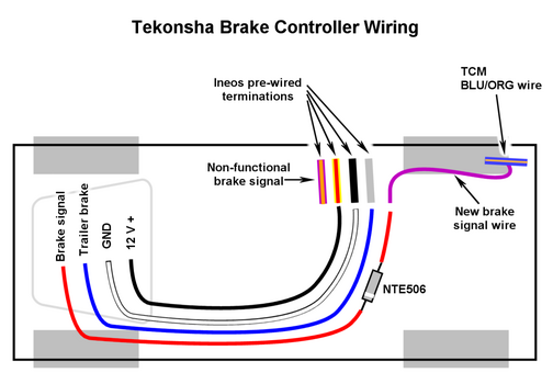
After reading through this thread, I chose to ignore the VIO/ORG wire under the rear seats and instead ran a new 18 AWG (VIO) wire from the TCM BLU/ORG wire at the right rear corner forward to the rear seat area. From there, I extended the Ineos brake controller pigtails with new wires under the rear seats to the outer edge near the left rear passenger door. I adopted Tekonsha's wire color scheme for the custom harness:
The 14 AWG RED wire for the brake signal is simply what I had on hand in that color – 18 AWG is adequate. I wouldn't go smaller than the gauges shown for the other three wires. The WHT ground would benefit from 12 AWG, but other ground paths compensate and I wanted to keep the bundle compact.
At the left rear passenger seat edge I installed a Deutsch connector, then continued all four wires forward in the door threshold wire chase, encased in 3/4" fiberglass sleeving. Corrugated nylon split loom was too bulky for the chase – fiberglass sleeving lies flat. The forward run terminates in a second Deutsch connector next to the OBD II port under the dash, with wires routed up behind the hood release panel. The Tekonsha pigtail connects there, covered in 1/2" fiberglass sleeving through the dash, transitioning to 1/2" nylon split loom beyond.
To pass the controller wires from the dash top down to the OBD II area, I relieved a 1/16" plastic web next to an air duct using a 5/8" hole saw I made from a length of thin-wall tubing. A borescope confirmed nothing was immediately behind the web before cutting.
Diode – Resolving the TCM Error Messages
My first test produced three error messages before I even connected the trailer: TCM error, TSA not available, and AEB not available. When I unplugged the brake controller, all three cleared immediately. Guidance in this thread from RedArc and Ineos pointed to the fix – a diode in the brake signal line (VIO). The diode allows current to flow from the TCM to the brake controller but blocks reverse flow.
I used a part already in my bin:
I retrofitted the diode into a short sub-harness with Deutsch connectors, inserted at the junction I had created under the left rear seat. The diode is soldered into uninsulated butt connectors – this prevents solder wicking into the stranded wire and makes any future diode replacement easy. The cathode band is oriented towards the brake controller.


Results
The diode eliminated all the relevant error messages. The one remaining message – a complaint about missing reverse lights on the trailer when shifting to Reverse is not really an issue. I may add a dummy LED on the trailer reverse circuit eventually, but it doesn't affect braking. Everything else works correctly: the controller displays applied voltage when braking, manual trailer braking is functional, and all trailer lights – running, brake, turn, and hazard – operate normally. Several test drives on steep local grades confirmed smooth, well-modulated braking with appropriate gain response.
For fun, here's a picture of our camp trailer hooked up to the GRINEOS. It has a maximum gross weight of 2900 pounds.

Let me know if I can answer any questions.
Glen
I chose the Tekonsha over other controllers for several reasons:
- Performs well on steep mountain grades and sharp turns.
- Clear display showing applied voltage plus status and error messages.
- Boost button that temporarily increases gain in three steps for extra load or steep terrain.
- Manual brake lever that is immediately accessible – no awkard mode switching required, unlike the RedArc.
The first task was finding a location that would survive driver entry and exit and remain accessible while driving. Mounting on the vertical dash face outboard of the steering wheel risked shin and foot contact and made the display hard to see. After reviewing the Customer Accessory Fitting Instructions in the Ineos Portal, I determined I could mount the controller on top of the dash in the rubber tray at the outer edge while staying clear of airbag deployment zones.
The rubber tray is held by three tabs that drop into matching holes. I positioned the base plate over the outer hole to route wires without cutting additional dash holes. The base plate is 1/8" aluminum with four #4-40 × 3/8" press-in studs and a center hole for the controller wires.
Here's how the rubber dash tray looks with a cutout for the base plate:
The base plate is adhered with 3M VHB tape. The controller mount is bent from 1/16" aluminum, secured to the base plate with #4-40 washers and nuts, and spaced off the plate with four nylon washers. Both parts are painted with Rustoleum Painter's Touch Charcoal Gray Satin – a close match to the interior. The large hole in each part aligns to pass the four brake controller wires.
Controller Installation
The controller is secured with #8-32 thumb screws – cleaner looking and easier to remove than conventional screws. From the driver's seat, the controller sits below the hood and fender line with no obstruction to forward visibility.
Wiring
After reading through this thread, I chose to ignore the VIO/ORG wire under the rear seats and instead ran a new 18 AWG (VIO) wire from the TCM BLU/ORG wire at the right rear corner forward to the rear seat area. From there, I extended the Ineos brake controller pigtails with new wires under the rear seats to the outer edge near the left rear passenger door. I adopted Tekonsha's wire color scheme for the custom harness:
Code:
Grenadier Wire Color    Function            Custom Harness Wire Color & AWG
--------------------    ---------------     -------------------------------
   YEL/RED                 12 V +               BLK 12 AWG

   BLK                     12 V -               WHT 14 AWG

   VIO (from TCM)          veh brake signal     RED 14 AWG

   GRY                     0 to 12 V +          BLU 12 AWG
                           trailer brake
The 14 AWG RED wire for the brake signal is simply what I had on hand in that color – 18 AWG is adequate. I wouldn't go smaller than the gauges shown for the other three wires. The WHT ground would benefit from 12 AWG, but other ground paths compensate and I wanted to keep the bundle compact.
At the left rear passenger seat edge I installed a Deutsch connector, then continued all four wires forward in the door threshold wire chase, encased in 3/4" fiberglass sleeving. Corrugated nylon split loom was too bulky for the chase – fiberglass sleeving lies flat. The forward run terminates in a second Deutsch connector next to the OBD II port under the dash, with wires routed up behind the hood release panel. The Tekonsha pigtail connects there, covered in 1/2" fiberglass sleeving through the dash, transitioning to 1/2" nylon split loom beyond.
To pass the controller wires from the dash top down to the OBD II area, I relieved a 1/16" plastic web next to an air duct using a 5/8" hole saw I made from a length of thin-wall tubing. A borescope confirmed nothing was immediately behind the web before cutting.
Diode – Resolving the TCM Error Messages
My first test produced three error messages before I even connected the trailer: TCM error, TSA not available, and AEB not available. When I unplugged the brake controller, all three cleared immediately. Guidance in this thread from RedArc and Ineos pointed to the fix – a diode in the brake signal line (VIO). The diode allows current to flow from the TCM to the brake controller but blocks reverse flow.
I used a part already in my bin:
- Manufacturer: NTE
- Part number: NTE506
- Reverse voltage: 1400 V
- Peak forward current: 35 A
- Max average forward current: 2 A
- Forward voltage drop: 1 V at 1 A
I retrofitted the diode into a short sub-harness with Deutsch connectors, inserted at the junction I had created under the left rear seat. The diode is soldered into uninsulated butt connectors – this prevents solder wicking into the stranded wire and makes any future diode replacement easy. The cathode band is oriented towards the brake controller.
Results
The diode eliminated all the relevant error messages. The one remaining message – a complaint about missing reverse lights on the trailer when shifting to Reverse is not really an issue. I may add a dummy LED on the trailer reverse circuit eventually, but it doesn't affect braking. Everything else works correctly: the controller displays applied voltage when braking, manual trailer braking is functional, and all trailer lights – running, brake, turn, and hazard – operate normally. Several test drives on steep local grades confirmed smooth, well-modulated braking with appropriate gain response.
For fun, here's a picture of our camp trailer hooked up to the GRINEOS. It has a maximum gross weight of 2900 pounds.
Let me know if I can answer any questions.
Glen
Attachments
Last edited:
