The Grenadier Forum

Register a free account today to become a member! Once signed in, you'll be able to contribute to the community by adding your own topics, posts, and connect with other members through your own private inbox! INEOS Agents, Dealers or Commercial vendors please use the contact us link at the bottom of the page.

Littelfuse FHZ busbars used in the Grenadier

In time I would like to see images of both busbars on the US models with the aux power option and inverter fitted. There should be one difference, at minimum, Stud 4 on the 7 Stud BB should have a cable to the inverter (and not a spare). Being a 2024 model they may also show some other changes.
 
Here are some pictures from today.
IMG_2429.jpeg
IMG_2434.jpeg
IMG_2442.jpeg


I removed the aux battery, 5 stud busbar, ctek, and related housing. I then rerouted the High Load panel wire to stud 7 as that wire had been removed with the 5 stud bb. The inverter cable is located on stud 4 of the 7 stud bb. That too will be removed for my particular build.
IMG_2444.jpeg


We will be placing a fridge in the now empty spot where the aux battery was. We will also be adding a lithium battery and components in the footwell space in front of the starter battery. More info is in the Build Thread.
 
Old thread, but I am in the middle of a project to install my ARB twin compressor and I am trying to install the power lead to the compressor on the open section of the 5 Pole Littlefuse buss bar. I have found the stud and the 40 amp fuse on-line, but I am not entirely sure I know how to install the stud. Anyone swapped out the studs, changed locations, etc? Just want to make sure I am not opening up a hornets nest as I can simply wire it to the positive terminal of the battery.
Thanks
 
I have changed a 40 amp to a 80 amp ZCASE MEGA fuse for my twin ARB compressor, on the 5 stud busbar.

Undo nut, replace or add the ZCASE MEGA fuse, attach compressor cable and secure the nut again. There are recommended torques settings based on the size of the bolt, see below. I cannot remember the bolt size off hand.

My compressor has been working fine for about 8 months.

screenshot-2023-09-15-05-14-32-png.7826854
 
I bought a spare busbar for parts and my spares kit. So I had a spare M8 bolt to add if I needed it, and I did on the 5 stud busbar. I also had a spare bolt on the 7 stud busbar which I could have moved across.

The compressor was originally going on 7 stud busbar but the cable was a little short and I told them they could use the 5 stud busbar (at the start if neeed) which was closer the compressor unit.
Thanks! I think that is what I am going to have to do (buy a spare). I can’t get the 8MM stud anywhere in the US. Since I have aux battery, etc the only open spot on both buss bars if #5 on the 2nd one.

How easy was it to put in the new stud? It appears you just push out the cover on the bottom and then install the new stud and clip the bottom cover back into place? Also - I am planning to purchase a 80 amps fuse for the twin compressor (40 amps per motor), but I am getting a little confused on the size of the hole in the fuse? The fuses appear to come in multiple sizes. The one I am planning to order is 3298080.H. I think this one has the 8MM hole, but using the same part number a couple of sites show it as 6MM and another site shows it at 10MM?
 
In the picture posted at the onset of this thread there is a picture of the 5 slot Busbar that looks just like mine, but it appears that the 60 amp fuse if one of the smaller 6MM types so curious if anyone know the various part number for the different size studs?
Thanks
 

Attachments

  • 5 STUD BUSBAR AU DxO.jpg
    5 STUD BUSBAR AU DxO.jpg
    485.3 KB · Views: 52
In the picture posted at the onset of this thread there is a picture of the 5 slot Busbar that looks just like mine, but it appears that the 60 amp fuse if one of the smaller 6MM types so curious if anyone know the various part number for the different size studs?
Thanks
That is the busbar from my car, as wired by the factory. I used a M8 bolt in the spare spot, from the spare busbar I bought (I bought a 5 stud because it was cheaper than a 7 stud). I was focused on ensuring the 80 amp fuse I needed to use, could take the M8 bolt. Mine is twin ARB air compressor. And that spare slot in the picture is the one I used.
 
How easy was it to put in the new stud? It appears you just push out the cover on the bottom and then install the new stud and clip the bottom cover back into place? Also - I am planning to purchase a 80 amps fuse for the twin compressor (40 amps per motor), but I am getting a little confused on the size of the hole in the fuse? The fuses appear to come in multiple sizes. The one I am planning to order is 3298080.H. I think this one has the 8MM hole, but using the same part number a couple of sites show it as 6MM and another site shows it at 10MM?
Real easy. I just played around with the spare busbar, once I worked out how it worked it was a very simple job. I removed the M8 bolt from the spare busbar, checked the 80 amp fuse could take the M8 bolt (it can), installed the bolt into the 5 stud busbar etc I was careful not to cause any accidental shorts with any tools, from memory I used a a couple of pierces of cardboard to cover things up. My car is 2 seater where there is no plastic trim like the 5 seater.
 
The spare busbar I bought only had M8 bolts. But M6 and M10 can also fit, so INEOS must have a supply deal with Littelfuse. The retail stores in Australia just have the one offering.

Someone here has used a normal bolt, the current is not going through the bolt but the fuse. I wanted the spare busbar and I knew I could use the bolts if I chose. For me it served two purposes.
 
Helo Guys , already went down this rabbit hole . :)
These are the part numbers :
908-066 M6 x 1.0 Thread Stud
908-067 M8 x 1.25 Thread Stud
908-068 M10 x 1.5 Thread Stud (38 mm)
Mouser used to have the M6 in stock but it seem no longer .


Best bet to get one is either buy a whole assembly , or try littlefuse directly or INEOS . To be fair they have been pretty good at getting people parts . (they have given me all i asked for)

Good luck .
 
Thanks guys. I was able to track down the spare part numbers on the studs from Littlefuse, but nobody has them in the US so going the route of ordering the entire 5 slot busbar so I have spare parts as well.

I have the twin ARB compressor as well and just curious if you know what 80 amp ZCASE fuse you used? I could get the one from INEOS, but that appears to be a on 6MM stud so I am guessing it will not fit the 8MM. Maybe it will, but the details on the Littlefuse site all show an 8MM hole opening.

I am also going to order some spare fuses and I want to make sure I get the correct ones. I “think” the “Starter” versions are all 10MM and the other are all 8MM, but will work with the 6MM stud? Any assistance would be greatly appreciated as I only really want to do this once.

Having looked at everything I think the correct part is 3298080.H

Thanks
1734914578406.png


1734914495995.png
 
TEIL 2 – WIE INEOS DIE LITTLFUSE- SAMMLUNGEN IM GRENADIER VERWENDET

HINTERGRUND

Die Stromschienenabdeckungen wurden zum Fotografieren entfernt. Nach dem Fotografieren wurden die Abdeckungen wieder angebracht.

Die Bilder stammen von einem Trialmaster Diesel (AU-Spezifikation, Baujahr 2023) mit der optionalen Zusatzschaltereinheit für hohe Lasten und einer montierten Frontwinde. Ich habe bereits genügend Bilder gesehen, um zu wissen, dass die genaue Konfiguration der Stromschienen variieren kann.

Hinweis: Überprüfen Sie immer Ihr eigenes Fahrzeug. Im Zweifelsfall wenden Sie sich an Ihren Händler oder Ihren Autoelektriker. Die Angaben wurden nicht von INEOS bestätigt. Mir sind keine technischen Daten bekannt, die INEOS zur Option „Hochlast-Zusatzschalterfeld“ veröffentlicht hat.
-------------------------------------------------------------------------------------------------------------

View attachment 7843521

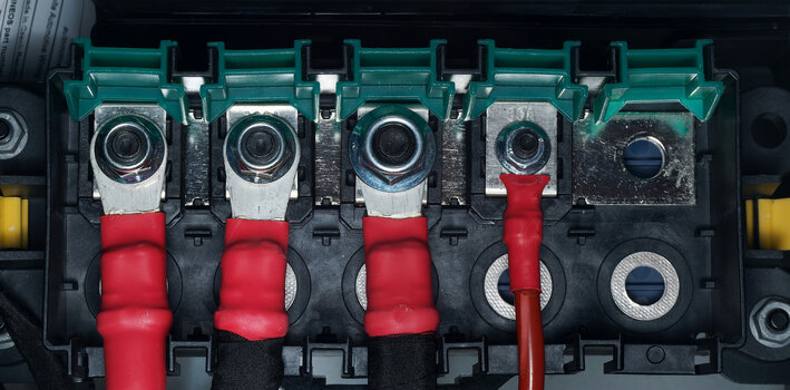
7-Loch-Sammelschiene*
Von links (1) nach rechts (7) sind die Ampere-Werte der ZCASE® MEGA-Sicherungen:
  1. Zuleitung von der Hauptbatterie, SHUNT, keine Sicherung. Schwarzes Klebeband;
  2. 125 Ampere für das Stromverteilungsmodul – Gelbes Band (RD/GN-Draht);
  3. 150 Ampere für die elektrische Innenausstattung – Blaues Klebeband (RD-Draht);
  4. Eine Ersatzsicherung mit 60 Ampere wird mit dem Bolzen mitgeliefert (für den optionalen INEOS 400-W-Wechselrichter; bei US-Modellen mit Wechselrichter sollte dieser Bolzen NICHT als Ersatzsicherung dienen).
  5. 100 Ampere für den elektrischen Verteilerkasten unter der Motorhaube – Grünes Klebeband (RD/VT-Draht);
  6. 125 Ampere für die elektrische Zentrale im Cockpit – Weißes Klebeband (RD/BU-Kabel); und
  7. SHUNT für das Zubehör des Vorsicherungskastens – Schwarzes Textilband mit weißem Etikett (wird an Bolzen 1 der 5-Bolzen-Sammelschiene angeschlossen).
Die Sammelschiene verfügt üblicherweise über einen Stromeingangsanschluss, der in der Regel mit einem ZCASE® MEGA Shunt für den Eingang kombiniert ist – siehe Installationsanleitung von Littelfuse hier. Ein Shunt befindet sich an Anschluss 1 (Zuleitung von der Hauptbatterie) und Anschluss 7 (Zuleitung zu Anschluss 1 der 5-poligen Sammelschiene).

*Abbildungen eines Trialmaster Diesel AU Spec 2023 mit der Option High Load Auxiliary Switch Panel und montierter Frontwinde.

-------------------------------------------------------------------------------------------------------------

View attachment 7843522

5-Loch-Sammelschiene*
Von links (1) nach rechts (5) sind die Ampere-Werte der ZCASE®MEGA-Sicherungen:
  1. SHUNT-Stromversorgung vom Innenraum des Vorsicherungskastens (kommt von Anschluss 7 der 7-poligen Sammelschiene);
  2. 300 Ampere für den CTEK SMARTPASS120S und den AUX-Luftkompressor (in AU-Ausführung);
  3. 350 Ampere für das Relais des hinteren NATO-Steckers;
  4. 80 Ampere für den Sicherungskasten der optionalen Hilfsschaltertafel für hohe Lasten; und
  5. Ersatzteil, Sicherung und Bolzen werden nicht mitgeliefert.
Die Stromschiene verfügt normalerweise über einen Stromeingangsanschluss, der üblicherweise mit einem ZCASE® MEGA Shunt für den Eingang kombiniert ist – siehe Installationsanleitung von Littelfuse hier. Anschluss 1 ist der Shunt an der 5-poligen Stromschiene (Sie können einfach das Wort SHUNT über dem Anschluss ablesen).

*Abbildungen eines Trialmaster Diesel AU Spec 2023 mit der Option High Load Auxiliary Switch Panel und montierter Frontwinde.

BEKANNTE ZCASE® MEGA-SICHERUNGSNENNEN, DIE IN GRENADIER VERWENDET WERDEN
Zu den bekannten Nennströmen der ZCASE® MEGA gehören: 80 Ampere, 100 Ampere, 125 Ampere, 150 Ampere, 300 Ampere, 350 Ampere und 3 Shunts.

View attachment 7843650

ZCASE® MEGA-SICHERUNGEN - ERSATZTEILE
Da die Stromschienen die Stromquellen für die Sicherungskästen sind, sollten die Besitzer überlegen, Ersatzsicherungen von ZCASE® bereitzuhalten, beispielsweise mit 80 Ampere, 100 Ampere, 125 Ampere und 150 Ampere.

ZCASE® MEGA-Sicherungen sind allerdings teuer. Wer nur lokal oder regional unterwegs ist, benötigt möglicherweise keine Ersatzsicherungen. Für Reisen in abgelegene Gebiete bleibt einem jedoch kaum eine andere Wahl, als Ersatzsicherungen mitzuführen, da ZCASE® MEGA-Sicherungen in Australien schwer zu beschaffen sind. Erfahrungsgemäß sind auch die anderen Sicherungstypen des Grenadier regional oder in abgelegenen Gebieten schwer zu bekommen. Für mich persönlich sind Ersatzsicherungen auf Reisen in entlegene Gebiete unerlässlich. Letztendlich muss jeder Besitzer die für seine Bedürfnisse beste Entscheidung treffen. Ich hoffe, dieser Beitrag hilft dabei.
 
Hello everyone, does anyone know where the cable with the yellow tape goes? What does “power distribution module” mean and what exactly does it do?
Best regards,
Michael
 
Hello everyone, does anyone know where the cable with the yellow tape goes? What does “power distribution module” mean and what exactly does it do?
Best regards,
Michael
@Rok_Dr may know.

On other cars the PDM can concern:
  1. Ignition Systems
  2. Fuel Pumps
  3. Cooling Fans
  4. Auxiliary Accessories
Probably the same with the INEOS.
 
Last edited:
Okay, that sounds a bit too complicated for me. I’d like to connect the 12V socket in the trunk to the auxiliary battery.
What do I need to do for that?


As far as I can see, the external sockets on the roof are switched via the cable connected to terminal 4 of the 5-pin power rail.
I’ve disconnected this 5-pin power rail from the 7-pin one and connected it directly to the auxiliary battery — and that worked.


For the auxiliary battery setup, I’ve installed two 150Ah LiFePO₄ batteries, together with a CTEK Smartpass 120S, a CTEK D250SA, and a solar panel on the hood.


Many thanks for the great pictures, Doc, and for the extremely helpful information!
 
@Rok_Dr may know.

On other cars the PDM can concern:
  1. Ignition Systems
  2. Fuel Pumps
  3. Cooling Fans
  4. Auxiliary Accessories
Probably the same with the INEOS.
If its the one that has a green stripe on the red insulation then it goes to the power distribution module. I have no idea as that the power distribution module does and what is connected to it at the moment.
 
If its the one that has a green stripe on the red insulation then it goes to the power distribution module. I have no idea as that the power distribution module does and what is connected to it at the moment.
I may need to revise the post.

EDIT: the cable is red with a green strip and also yellow tape. Second from left. Are we both talking about the same cable to the PDM?

7-stud-busbar-au-dx-jpg.7843521
 
Back
Top Bottom