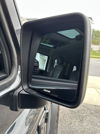
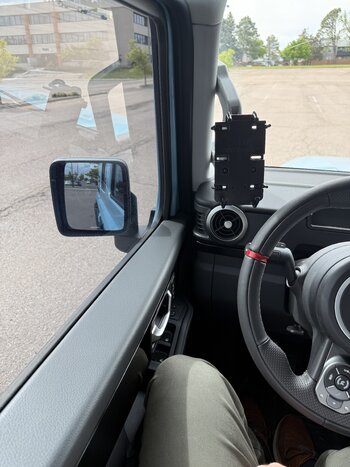
In my new member introduction post, I mentioned that half the view in my driver's outside mirror (LHD here in the US) was showing me the side of the vehicle and that I had modified the mirror to allow it swing farther out. Member
@IG Pop asked how I did that, so here are the steps involved:
1) Pry off the triangular trim cover on the bottom of the mirror bracket with a plastic trim tool. There is a tab at the outermost edge of the cover and a second and third tab on the front and back edges. These tabs have square protrusions at the top for retention, so work carefully and try to ease these out without breaking them.
View attachment 7916420
2) Remove the mirror glass. I centered the mirror left & right, moved it to maximum up, then used my fingers on the lower edge of the glass to pry it off the motor drive. Then (if present) gently unplug the mirror heater wires.
3) Remove 3 Torx screws holding the motor drive to the black plastic mirror frame. The motor drive is now hanging by its wiring harness.
4) Remove the 3-wire connector from the motor drive and set the motor drive aside. Each retention clip for the wiring connector has a very large bump to retain the connector - so large I thought it would break the retention clips before the connector was free. Before removing the connector, I used a new razor blade and cut the bumps to half their original width. This still allows retention of the connector but doesn't threaten to break the retention clips upon connector removal.
5) Depin the three wire connector. First flip up the hinged retention gate on the back of the white plastic connector where the wires exit, then use a very small flat blade screwdriver or a depinning tool and depress the barb on each connector from the front and pull the wire out of the connector from the back.
6) From below, remove 3 Torx screws securing the mirror housing to the door mount. These screws are not under any tension. Hang onto the mirror when you remove the last screw, then gently remove the mirror housing by pulling up and feeding the 3 motor drive wires and the mirror heater wires (if present) down through the hollow stem of the mirror. The wires remain attached to the vehicle when the mirror housing is free. With the mirror housing free of the vehicle, you can move it to a bench and continue disassembly.
7) Remove 3 Torx screws that secure the back half of the outer mirror housing (the side you see from the driver's seat) to the front half of the outer mirror housing. These screws go through the black glass-filled nylon mirror frame. With the 3 screws removed, you'll be able to remove the two outer housings and are left with just the glass-filled nylon mirror frame and the cast aluminum spring-loaded base.
View attachment 7916421
Some explanation of how the mirror is assembled is in order. The black plastic mirror frame contains a hollow plastic pivot tube that is inserted from the top. This tube has a head and under that is a flat plastic washer (white) and then a blue plastic washer with a lip that locates the base of a coil spring. The lower end of this hollow plastic tube has 4 protrusions that lock into a matching receptacle in the cast aluminum mirror base. The mating faces of the plastic mirror frame and the aluminum base each have 3 protruding detents and 3 valleys between them. The protrusion of one matches the valley in the other. When the mirror is folded forward or backwards, the coil spring is compressed and the protrusions ride up over each other until they seat in the next valley. We're going to modify the protrusions so the mirror can be rotated farther away from the driver's door.
View attachment 7916422
8) You'll need to find a couple of objects and make 2 tools for the next step.
(a) I made the first tool from a 2" square of 1/2" plywood: drill two 1/8" holes in the plywood that match the protruding locating pins on the cast aluminum mirror base (these pins are right next to the 3 screw holes that mount the mirror to the vehicle). Locate the holes so that the plywood is centered on the cast aluminum mirror base - this will provide a surface for a bar clamp jaw in a later step.
(b) I made the second tool from 1/8" welding rod: this tool is used to turn the hollow tube once it is compressed with a bar clamp. I used a 10" long piece of welding rod and bent it 180° just beyond the halfway point. This gave me a U-shaped piece with the ends offset (in length) by about 1/4". Then I bent the two free ends down at 90° so they could be inserted into the matching pair of slots in the top of the hollow plastic pivot tube. I bent about a 1/2" length of rod down, then trimmed them with diagonal cutters to about 3/16" long and filed the ends flat with a file. The tool should have the minimum height necessary to fully engage the slots in the head of the hollow plastic bolt and not much more.
(c) The last tool you'll need is something to push on the head of the hollow plastic tube. I found that a short 3/8" drive socket extension plus a 3/8" finger socket driver on top worked perfect. (See an example of a finger driver
here.) The extension bar drops into the hollow tube a short distance - stabilizing it from side to side - and the larger end of the extension sits on top of the hollow tube head (it's too large to pass thru). The extension bar must be shorter than the hollow tube and not interfere with the plywood tool you made in step (a).
View attachment 7916423
9) Take a look at the bottom of the mirror assembly. You'll see the hollow plastic tube is captured in the cast aluminum base by 4 protrusions on the tube. The protrusions slide down 4 lengthwise slots in the plastic mirror frame, continue into the cast aluminum base and then twist to lock into 4 matching receptacles. One side of each receptacle has a very short wall - this is the wall the protrusions must clear when the spring is compressed - and the other side has a very tall wall the protrusions seat against and will not pass.
With the plywood tool seated on the two locating pins of the base and the socket extension + finger driver at the other end of the hollow tube, use a bar clamp to compress the spring inside the mirror frame. Orient the clamp so that the 1/8" welding rod tool will have access to turn the hollow tube clockwise 1/8 turn. The spring is too stiff to compress by hand (with any kind of control), but a bar clamp will easily compress the spring. The spring will compress about 1/2" and stop - don't exert any extra pressure once the spring stops moving since this will make it harder to turn the hollow tube in the next step.
10) With the spring compressed and viewing the assembly from the top (the head side of the hollow tube), use the welding rod tool to turn the hollow tube 1/8 turn clockwise. If the tube won't turn, the spring is either not compressed fully or the clamp is so tight that friction prevents turning the hollow bolt. With the clamp properly situated, it should only take about 10 pounds of force to turn the hollow bolt.
11) Slowly remove the clamp, relieving the coil spring tension as the clamp is removed. Then remove the hollow bolt with its 2 plastic washers and the coil spring. The cast aluminum base is now free of the plastic mirror frame.
12) When looking at the detent side of the cast aluminum mirror base, three raised protrusions are visible. For each protrusion, we'll need to remove a section on the leading edge of a clockwise rotation (as viewed from the top) that is about 2 mm deep and extends 6 mm along the outer edge.
View attachment 7916424
13) A small square file works well to modify the aluminum base. Don't file any deeper than the inner raised ring of the base . The finished material should have an approximately 45° ramp angle, just like the original part. While filing the 45° angle, the centerline of the file should be aimed at the center of the hole in the part - this will result in the modification lining up with the mating plastic part. I used a small pattern maker's file to smooth the rough surface left by my square file, but it doesn't need to be extraordinarily smooth. This completes the modification.
Here's a photo with the last material removal in progress:
View attachment 7916425
And here's the finished result. The depth of the material removed matches the inner ring.
View attachment 7916426
14) Before assembly, I applied some silicone grease to the face of the aluminum detents (replicating what I cleaned away before filing). I recommend leaving this joint free of grease if you don't plan on frequently folding the mirror in and out since the added friction will help keep the mirror in the desired position.
15) Assembly, as they say, is the reverse of disassembly. Here are a few notes that may be helpful:
(a) The hollow tube parts stack up is
hollow tube | white flat washer | blue cupped washer | coil spring
This gets inserted down into the mirror base. Upon insertion, the tube is initially aligned by slots in the mirror frame matching the 4 protrusions on the tube. But the tube will spin freely when fully inserted . . . don't let it spin. The original position will align with the cast aluminum mirror base and you'll need it to be aligned before compressing everything with a bar clamp. These parts will only go together in the *original* position imposed by the *original* detents. So line the parts up as if you had not modified anything, then install the bar clamp and compress the spring.
(b) After compressing the assembly with a bar clamp, use the welding rod tool to turn the hollow tube 1/8 turn counter clockwise to secure it. Carefully remove the bar clamp then inspect the bottom end of the mirror assembly to ensure the hollow tube protrusions are fully seated.
(c) When reassembling the motor drive connector, the order of wires as viewed from the back of the motor drive with the connector installed at the top is (left to right) red | green | yellow. Alternately, the labelled pins are 1 = red, 2 = grn, 3 = yel.
View attachment 7916427
(d) The mirror manufacturer used tri-lobe thread forming screws for the three fasteners to secure the mirror base to the vehicle (these are the screws you removed in step 6 above). In my experience, these are meant for only one insertion and can easily strip a threaded hole in aluminum when removed and reinserted. YMMV. After chasing the threads in the cast aluminum base with an M5 x 0.8 bottoming tap, I replaced the 3 tri-lobe screws with regular M5-0.8 x 15 mm Allen head screws of the same length.
(e) Before reinstalling the triangular cover on the bottom of the mirror mount, I used a new razor blade to cut a ramp on the retention clip protrusions so that they will slide out more easily upon the next removal, then lubricated them with some Vaseline.
(f) Prior to snapping the mirror glass back in place, I lubricated the plastic retaining tabs on the mirror mount with some Vaseline. This makes installation or removal much easier and less likely to break a tab. Don't forget to plug in all the wires before snapping the glass in place.
That's it. These are a lot of fussy steps and the locating result is not as positive as the OEM part. To remedy both of these problems, I've ordered a second mirror assembly that I will use to protoype what I hope will be a bolt-on solution that's easy to install without special tools and provides a positive detent just like the OEM part. More to come . . .


")