Ok, this is not straightforward but it is longwinded. Grab a coffee...
- I found an undated copy of the BreakSafe series 6000 manual with a wiring diagram posted by AOR here and probably a current but also undated download available from the manufacturer RV Electronics here.
- The copy from AOR says to wire the BreakSafe charger to the auxiliary line on pin 2. The current copy from RV has deleted the reference to pin 2 and says to wire the charger to the auxiliary line.
- Oddly, pin 2 was never the auxiliary line in the 12 pin wiring standard via AS4177.5-2004.
- This 2021 Jayco document shows pin 2 as the auxiliary line so perhaps the BreakSafe instructions were originally written for Jayco non-standard standard wiring
 .
.
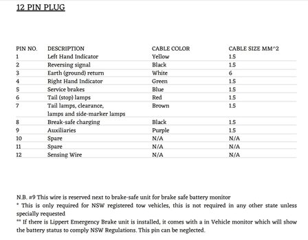
- In AS4177.5-2004 pin 2 is the reverse signal pin which is mostly unused. The Auxiliary is pin 9.
- On pages 14 and 15 of this May 2025 Jayco document pin 8 is Batt+ and Pin 9 is unused in typical Jayco wiring installations.
So much for wiring standards huh?
Why does any of that matter:
Your caravan wiring diagram is expecting a BreakSafe charging current on
pin 8. That's a Batt+ pin and complies with AS4177.5-2004 (the standard that Narva use).
But that's not the Auxiliary pin that RV Electronics say to use in their current BreakSafe wiring instructions. I cannot find anything conclusive but I think pin 8 is constant +12v and pin 9 is supposed to be ignition switched +12v.
That difference aside, either pin 8 or 9 will supply +12v to the BreakSafe charger when your tow vehicle is running. Pin 9 is a better choice because it's ignition switched so it won't add another drain to your tow vehicle battery if the caravan is plugged in and your vehicle is not running.
For example,
this AOR document has the BreakSafe charger powered through pin 9.
Sooo.....
If your previous tow vehicle was wired to the 12 pin standard AS4177.5-2004 everything should have worked when you plugged in directly. Pin 8 was charging your Breaksafe unit. Happy days

But now you're using an adapter to a 13 pin Euro socket and all bets are off.
Here's a comparison of 12 pin versus 13 pin functions. I've added bold to highlight to the power circuits we're discussing.
(The forum software hates data tables)
| Wire colour | 12 pin Aust | Pin # | Wire colour | 13 pin Euro |
| Yellow | Left-Hand Turn | 1 | Yellow | Left-hand direction indicator light |
| Black | Reversing Signal | 2 | Blue | Rear fog light |
| White | Earth Return | 3 | White | Common return for contacts no. 1 to 8 |
| Green | Right-Hand Turn | 4 | Green | Right-hand direction indicator light |
| Blue | Service Brakes | 5 | Brown | Right-hand rear, position and marker lights and license plate lamp |
| Red | Stop Lamps | 6 | Red | Brake lights |
| Brown | Rear Lamps, Clearance and Side Markers | 7 | Black | Left-hand rear, position and marker lights and license plate lamp |
| Orange | Battery Charger | 8 | Pink | Reversing light |
| Pink | Auxiliary /Batt + | 9 | Orange | Power supply (steady, constant) |
| White | Earth Return | 10 | Grey | Power supply controlled by ignition switch |
| Grey | Rear Fog Lamp | 11 | White/Black | Common return for pin 10 |
| Purple | Auxiliaries | 12 | - | Reserved for future allocation |
13 | White/Red | Common return for pin 9 | | |
I'll assume Vanline's adapter follows AS4177.5-2004 at the 12 pin end and ISO 11446 at the 13 pin end just like above. The 13 pin ISO11446 deets come from
here.
Vanline will have cross-mapped the pins so everything works, kinda. Straightoff you can see a couple of problems though:
- Pins 5 and 7 of the 13 pin standard need to be combined onto pin 7 of the 12 pin standard. This also needs diodes installed to work properly. The Narva adapter has this. Presumably the Vanline adapter does also.
- There is no pin 5 service brake (electric trailer brakes) in the 13 pin standard.
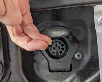
To keep it interesting, Ineos (or Magna, or Aptiv) didn't fully follow ISO11446 in the early builds. Pins 10, 11 and 12 were not fitted (pic). Maybe this only affects MY23 builds. Not a huge consequence but it means the IGN+ passthrough circuit is missing.
I have seen evidence that this changed for MY24 AUS/NZ delivered vehicles and the wiring functions were changed to make the 13 pin Euro work better with Aus 7 and 12 pin adapters, plus the incorporation of wiring (only?) for electric service brakes. More on this below.
MY23 13 pin Euro plug (Aus delivered vehicle)
View attachment 7915183
Testing
So back to your question
@etbandit. It depends!
If Vanline connected pin 8/12 to pin 9/13 in their adapter it should work already. Plug in the adapter to the Grenadier and put a voltmeter across pin 8/12 (+12v) and pin 3/12 (ground) and see what you have.
> You will hopefully get constant power (key off) on pin 8/12 if Vanline wired pin 8/12 to pin 9/13.
Repeat this test with pins 9/12 and 3/12.
> You will probably not get any power on pin 9/12 because Vanline wouldn't know that Ineos didn't wire pin 10/13.
Please post back here with the results.
Note: Have you done something about your service brake circuit?
Is AUS/NZ MY24 different?
I've seen another wiring diagram that shows on MY24 AUS and NZ vehicles pins 3/13 and 10/13 are chassis grounds and pin 5/13 is wired for a service brake. Probably just wiring provisions back to the trailer module. I've not heard of any AUS/NZ vehicles delivered with a complete factory electric brake controller.
I'd love for someone to confirm these MY24 differences for AUS/NZ only:
| 13 pin Euro. ISO 11446. AUS/NZ MY24 | |
| Pin | Function |
| 1 | Left-hand direction indicator light |
| 2 | Reversing light |
| 3 | Chassis Ground for pins 1-7 |
| 4 | Right-hand direction indicator light |
| 5 | Service Brake (pass through only or controller?) |
| 6 | Brake lights |
| 7 | Left-hand and right hand position lamps |
| 8 | Power supply (steady, constant) |
| 9 | - |
| 10 | Chassis Ground for pins 8 and 11 |
| 11 | Fog lamps |
| 12 | - |
| 13 | - |
HTH. I'm going for a lie-down