The Grenadier Forum

Register a free account today to become a member! Once signed in, you'll be able to contribute to the community by adding your own topics, posts, and connect with other members through your own private inbox! INEOS Agents, Dealers or Commercial vendors please use the contact us link at the bottom of the page.

Front Suspension Lower Control Arm Torque Specs

@Glen my bad, torque is actually 295Nm for that 928 bolt.
 
I obtained replacement parts from the dealer and replaced the fasteners that secure the front axle lower control arm to the chassis.

I took some measurements of the original bolts and the new ones. The measurements of diameter were taken at seven equally spaced points between the flanged bolt head and just above the washer retention groove along a line above the groove for Diameter 1 and at 90° to that line for Diameter 2. Lengths were measured from the shortest edge of the flanged bolt head to the end of the bolt. All dimensions are in inches.

Code:
Original Bolt 1     
Length    Station    Dia. 1    Dia. 2    Notes
4.488        1       0.5430              closest to threads
             2       0.5430              no significant difference Dia. 1 vs Dia. 2
             3       0.5450
             4       0.5460
             5       0.5455
             6       0.5460
             7       0.5475              closest to head

Original Bolt 2      
Length    Station    Dia. 1    Dia. 2    Notes
4.491       1        0.5420    0.5425    closest to threads
            2        0.5460    0.5443
            3        0.5450    0.5460
            4        0.5445    0.5450
            5        0.5450    0.5460
            6        0.5455    0.5460
            7        0.5465    0.5465    closest to head
      
New Bolt 1      
Length    Station    Dia. 1    Dia. 2    Notes
4.467       1        0.5420              closest to threads
            2        0.5425              no significant difference Dia. 1 vs Dia. 2
            3        0.5440
            4        0.5440
            5        0.5450
            6        0.5460
            7        0.5465              closest to head
      
New Bolt 2      
Length    Station    Dia. 1    Dia. 2    Notes
4.475       1        0.5420              closest to threads
            2        0.5425              no significant difference Dia. 1 vs Dia. 2
            3        0.5440
            4        0.5440
            5        0.5450
            6        0.5460
            7        0.5465              closest to head

4671.jpg


DISCUSSION OF MEASUREMENTS
I don't believe the lengths are significant enough to draw any reliable conclusions. The best way to detect stretch is to measure the bolt before and after stretch, and that wasn't done here. The bolt blanks are likely chopped to length in a non-precision process, heated, headed, stamped for the groove, then the threads and lead-in at the end are rolled. The last steps are likely heat treating and then plating. These steps don't result in precision starting lengths, although I would note the longest original bolt is 0.024" longer than the shortest new bolt.

Original Bolt 2 is the most interesting: the measurements show about 0.001" thinning at the midpoint of the no-thread shank. This bolt is also out-of-round by about 0.001" to 0.002". The new bolts were as close to round (as measured at two points offset 90°) as I can measure accurately. I did not measure diameter across the threads because I'd expect a lot of natural variation in diameter there due to the manufacturing process.

OTHER OBSERVATIONS
There was some very minor thread damage on both of the original bolts where the bolt threads exited the nut (towards the bolt head). When I placed a tap with a 1.5 mm thread pitch on the two original bolts, the tap would not seat perfectly into the threads. This indicates the threads were likely stretched, but unfortunately, I did not test the new bolts with this procedure. Since the cross section is smaller across the threads, it makes sense that any plastic deformation would be more likely to occur in the threaded section.

CONCLUSIONS
I can't really come to any definite conclusions here. My assessment from just visually inspecting the orginal bolts is that they would be suitable for re-use. My measurements and check of the thread pitch leads me to believe that at least one - and maybe both - of the bolts just barely got into plastic deformation, albeit a very small amount. Like others, I'll be interested in a reply to my query of Ineos.
 
Last edited:
I obtained replacement parts from the delaer and replaced the fasteners that secure the front axle lower control arm to the chassis. I took some measurements of the original bolts and the new ones. All dimensions are in inches.

<table>
<tr>
<th colspan="5">Original Bolt 1</th>
</tr>
<tr>
<th>Length</th>
<th>Station</th>
<th>Dia. 1</th>
<th>Dia. 2</th>
<th>Notes</th>
</tr>
<tr>
<td>4.488</td>
<td>1</td>
<td>0.5430</td>
<td></td>
<td>closest to threads</td>
</tr>
<tr>
<td></td>
<td>2</td>
<td>0.5430</td>
<td></td>
<td>no significant difference Dia. 1 vs Dia. 2</td>
</tr>
<tr>
<td></td>
<td>3</td>
<td>0.5450</td>
<td></td>
<td></td>
</tr>
<tr>
<td></td>
<td>4</td>
<td>0.5460</td>
<td></td>
<td></td>
</tr>
<tr>
<td></td>
<td>5</td>
<td>0.5455</td>
<td></td>
<td></td>
</tr>
<tr>
<td></td>
<td>6</td>
<td>0.5460</td>
<td></td>
<td></td>
</tr>
<tr>
<td></td>
<td>7</td>
<td>0.5475</td>
<td></td>
<td>closest to head</td>
</


<table>
<tr>
<th colspan="5">Original Bolt 2</th>
</tr>
<tr>
<th>Length</th>
<th>Station</th>
<th>Dia. 1</th>
<th>Dia. 2</th>
<th>Notes</th>
</tr>
<tr>
<td>4.491</td>
<td>1</td>
<td>0.5420</td>
<td>0.5425</td>
<td>closest to threads</td>
</tr>
<tr>
<td></td>
<td>2</td>
<td>0.5460</td>
<td>0.5443</td>
<td></td>
</tr>
<tr>
<td></td>
<td>3</td>
<td>0.5450</td>
<td>0.5460</td>
<td></td>
</tr>
<tr>
<td></td>
<td>4</td>
<td>0.5445</td>
<td>0.5450</td>
<td></td>
</tr>
<tr>
<td></td>
<td>5</td>
<td>0.5450</td>
<td>0.5460</td>
<td></td>
</tr>
<tr>
<td></td>
<td>6</td>
<td>0.5455</td>
<td>0.5460</td>
<td></td>
</tr>
<tr>
<td></td>
<td>7</td>
<td>0.5465</td>
<td>0.5465</td>
<td>closest to head</td>
</tr>
</table>
`


<table>
<tr>
<th colspan="5">New Bolt 1</th>
</tr>
<tr>
<th>Length</th>
<th>Station</th>
<th>Dia. 1</th>
<th>Dia. 2</th>
<th>Notes</th>
</tr>
<tr>
<td>4.467</td>
<td>1</td>
<td>0.5420</td>
<td></td>
<td>closest to threads</td>
</tr>
<tr>
<td></td>
<td>2</td>
<td>0.5425</td>
<td></td>
<td>no significant difference Dia. 1 vs Dia. 2</td>
</tr>
<tr>
<td></td>
<td>3</td>
<td>0.5440</td>
<td></td>
<td></td>
</tr>
<tr>
<td></td>
<td>4</td>
<td>0.5440</td>
<td></td>
<td></td>
</tr>
<tr>
<td></td>
<td>5</td>
<td>0.5450</td>
<td></td>
<td></td>
</tr>
<tr>
<td></td>
<td>6</td>
<td>0.5460</td>
<td></td>
<td></td>
</tr>
<tr>
<td></td>
<td>7</td


<table>
<thead>
<tr>
<th colspan="5">New Bolt 2</th>
</tr>
<tr>
<th>Length</th>
<th>Station</th>
<th>Dia. 1</th>
<th>Dia. 2</th>
<th>Notes</th>
</tr>
</thead>
<tbody>
<tr>
<td>4.475</td>
<td>1</td>
<td>0.5420</td>
<td></td>
<td>closest to threads</td>
</tr>
<tr>
<td></td>
<td>2</td>
<td>0.5425</td>
<td></td>
<td>no significant difference Dia. 1 vs Dia. 2</td>
</tr>
<tr>
<td></td>
<td>3</td>
<td>0.5440</td>
<td></td>
<td></td>
</tr>
<tr>
<td></td>
<td>4</td>
<td>0.5440</td>
<td></td>
<td></td>
</tr>
<tr>
<td></td>
<td>5</td>
<td>0.5450</td>
<td></td>
<td></td>
</tr>
<tr>
<td></td>
<td>6</td>
<td>0.5460</td>
<td></td>
<td></td>
</tr>
<tr>
<td></td>
<td>7</td>
<td>0.5465</td>
<td></td>
<td>closest to head</td>
</tr>
</tbody>
</table>
Whoa!
 
@Tazzieman - Sorry about that - this bulletin board totally screws up the TABLE tag and turns it into garbage. After three attempts I finally just posted plain text in a CODE block. See above for a more readable presentation.

@Stu_Barnes - can someone fix how TABLE code renders? I'm happy to provide examples offline if it'll help.
 
Ineos sent me an update today saying that they have verified the issue I identified is a problem and they are working to provide a resolution as quickly as possible.

In the interim, I found this post containing the same procedure of 110 Nm + 180° more. I presume this document presented was generated by Ineos engineers, but there is no certain attribution. I sure hope the 110 Nm + 180° procedure turns out to be wrong . . . by my investigation, that would mean the bolts need to be replaced every time they are loosened.
 
Last edited:
Glen, I like how you think.

Given the only way to adjust caster is to loosen the front lower control arm bolts it could suggest that any time an alignment is performed the control arm bolts need to be replaced. This is madness.
 
Ineos contacted me today to say their engineers are actively working to resolve the problem I described and they will notify me as soon as they achieve a resolution.

If it was a case of one or the other procedure is correct, you’d think the correct one would be quickly identified. So maybe this is a clue that neither procedure provides the intended outcome and they have to do some analysis of the joint to determine what’s required of the fastener. Hopefully . . . it could just be it’s problem #42 in the queue.
 
Forty days after my initial contact, I prompted Ineos for a reply to my inquiry:

. . .​

I want to personally apologize for the delay in my response; I didn't notice a system error that prevented me from seeing the follow-up sent by the engineers, and I only realized it today.

I'm really sorry for keeping you waiting for such a long time.

As for your inquiry, the engineers have confirmed that the official procedure is to apply 110Nm followed by the angle tightness.

They also asked me to express their gratitude for the effort you put into reviewing the process. They truly appreciate your work.

Thanks again for your patience and understanding.

If you need any further assistance or clarification, please feel free to reach out; I'm here to help.

Best Regards,

INEOS Automotive Customer Care Team

So the correct torque spec is 110 Nm + 180° additional rotation. The workshop manual appears to have been updated to remove the incorrect references to 190 Nm. The parts listing does not show the bolt as needing replacement and since the torque spec seems so close to the proof load of the fastener, I'll ask them to confirm the bolt is reuseable.
 

Attachments

  • GRA-0000-003440.png
    GRA-0000-003440.png
    354.8 KB · Views: 10
I wrote INEOS on March 12 and asked them to confirm the M14 bolt is REUSABLE. Here's what I wrote:

. . .
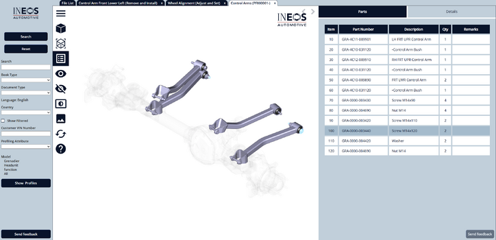
The parts listing does not designate the bolt in question (GRA-0000-003440) as single use for either the front or rear axle control arms. The confirmed torque spec of 110 Nm + 180° additional rotation seems to be very close to the proof load of a class 10.9 zinc plated M14 x 1.50 bolt. Can you confirm this part is intended to be reused?

An example of a part that is designated as single use is the propshaft screw set GRA-5D00-019750.
. . .

I figured I'd get a pretty quick answer since this information should have been considered long before now. Almost two weeks later - still no answer. That doesn't bode well . . . it makes me think someone said "Uh oh - we need to check this again."

I've been installing a Tekonsha trailer brake controller in my Grenny over the last few days. That requires pulling an awful lot of dash and interior panels to route the wiring properly. I'd had enough of the stress of almost (but not quite) breaking panels with unknown fixings, so for a break, I decided to build a bolt tension calculator that could model the INEOS specification for the M14 bolt in question here. I did look for on line calculators first, but none could handle both the initial torque and the advance.

So here is the output of my Excel-based calculator. The math is based on the formulas of VDI 2230 with fastener data from ISO 724, ISO 898-1 and ISO 68-1 that I can extract from search engines. These documents are generally copyright protected and quite expensive (ISO 898-1 is available for only CHF 204), with most publicly available versions just an extract of a few pages, so that's why the reliance on search engines. Note that there are many variations on how to calculate this data, so every calculator is likely to deviate slightly from another - but they will all generally be in the same ballpark.

bolt tighening procedure.png


The key data to observe is this:

- Elongation that results in yield: 0.4405 mm
- Elongation from initial torque: 0.1438 mm
- Elongation from 180° advance: 0.7500 mm
- Total Elongation: 0.8938 mm (if deformation is elastic)

Note that just the elongation from the 180° advance (let alone the total elongation) is almost double what is required to cause the bolt to yield. That's absolutely a one-use bolt!

The procedure specified by INEOS pushes the fastener FAR beyond the elastic limits of the bolt. Clamping force would be limited by the yield strength of 117.1 kN. I've compared the output of this calculator to other online calculators (examining the relationship of the initial torque to clamping force) and the results are quite similar. Regarding a sensitivity analysis, these calculations are not very sensitive to values for µ, Young's modulus values for medium carbon steel are very narrow (200 GPa - 215 GPa) and the mean nut bearing face calcuation has a very small effect on the results. All the other data are look up values and probably not subject to much debate. The single factor with the most effect on results is the fastener effective grip length and this is something I actually measured on my Grenadier, so it's pretty accurate.

Here are some sample inputs and outputs derived from the worksheet:
- 45 Nm initial torque + 60° advance = 70% of yield load
This probably isn't a good idea since the actual values achieved would probably have a pretty wide range around 45 Nm.

- 235 Nm torque + no advance = 70% of yield load
This torque value is a little higher than what you'd typically you'd find in a look up table, likely because the flange nut is absorbing more torque than a standard nut face would. Lookup tables would specify 190 - 195 Nm.

- 110 Nm initial torque + 40° advance = 70% of yield load
This might be okay, but I'm not sure how much more accurate this would be than just applying 235 Nm.

70% - 75% of yield load is a common target. The headroom below 100% is to make sure the tightening procedure doesn't get into plastic deformation. Torque wrenches are the least accurate way to torque a fastener, but they are also the most widely available method outside of a production environment. Using fasteners multiple times, the cleanliness of the joint, variations in plating and many other factors all conspire to make the actual values achieved with a torque wrench a pretty wide scatter.

I've attached the Excel file for those who want to play with different values. This file was built in Microsoft Office 2021 Pro.

Cheers!

edit: updated data to reflect the large flange nut vs a standard nut
 

Attachments

Last edited:
Back
Top Bottom