Hi all, I have an older model arb compressor that was in a box. I am mounting it under the back seat using the Euro Flo mounting bracket. I'm leaving the switch (mount modified) and the outlet in its original position until i set up drawers in the rear of the car.
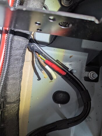
My question is, as I am using the original wiring harness, which has + & - leads, do I connect the red wire to the power or to the ignition wire located under the seat, already wired to 40 amp fuse? Black lead goes to earth point in floor. I only want it to be available when car is on.
Can anyone explain this? In simple terms?
Thanks
Pedro