Hi,
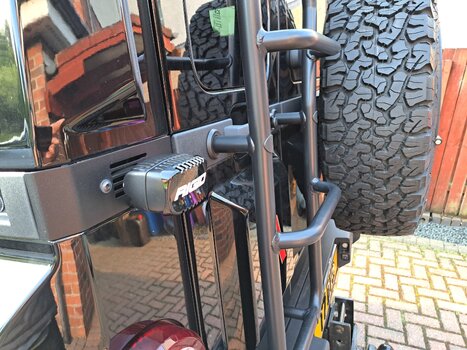
I'm looking for some guidance/ help. I am planning to install some spotlights on the front bumper, was looking to wire these through a relay into the mainbeam circuit, info gained from another thread.
The spots in question have backlighting which I was also wanting to utilise. I had hoped these would be on whilst either the DRL's, sidelights, headlights were on.
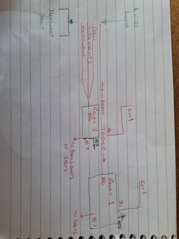
Question - can I take a trigger from each feed to a single relay to do this? Can something be introduced to each feed to stop current going back into the other two ?
They'll both be fed from ext 1 as the combined draw is 8amps.
Diagram attached to hopefully make it clearer.
As you can probably guess I am limited in my knowledge in electrics but always keen to learn something new.
Thanks
G.
I'm looking for some guidance/ help. I am planning to install some spotlights on the front bumper, was looking to wire these through a relay into the mainbeam circuit, info gained from another thread.
The spots in question have backlighting which I was also wanting to utilise. I had hoped these would be on whilst either the DRL's, sidelights, headlights were on.
Question - can I take a trigger from each feed to a single relay to do this? Can something be introduced to each feed to stop current going back into the other two ?
They'll both be fed from ext 1 as the combined draw is 8amps.
Diagram attached to hopefully make it clearer.
As you can probably guess I am limited in my knowledge in electrics but always keen to learn something new.
Thanks
G.
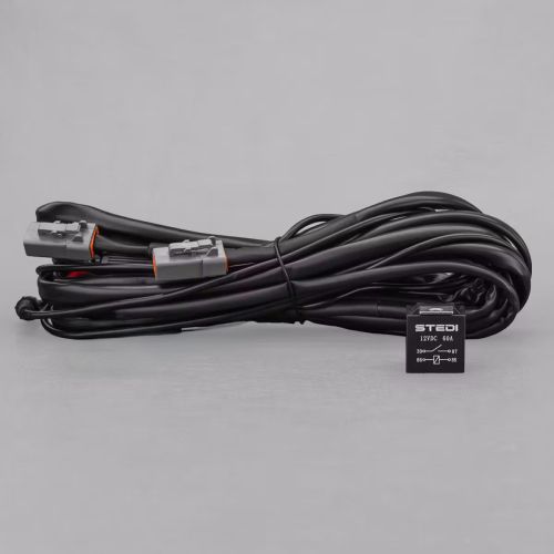

 for the spots.