The Grenadier Forum

Register a free account today to become a member! Once signed in, you'll be able to contribute to the community by adding your own topics, posts, and connect with other members through your own private inbox! INEOS Agents, Dealers or Commercial vendors please use the contact us link at the bottom of the page.

Low range will not engage after transfer case selector replacement

Manuel4x4

Grenadier Owner
Lifetime Supporter
Founding Guard
Local time
8:18 PM
Joined
Oct 12, 2021
Messages
93
Hi everyone,


I collected my Grenadier from the dealer after they replaced the transfer case selector because the linkage pin had come out.


The differential locks now work correctly, but low range will not engage.


The lever moves, but it seems the transfer case is not going fully into low range.


The dealer also did several warranty jobs (door locks, campaigns, etc.), so I suspect the transfer linkage might not be correctly adjusted after the selector replacement.


Has anyone experienced this after a selector or linkage repair?


Does it sound like a linkage adjustment issue, or could something else be wrong?


Thanks in advance.
Two possibilities a) simple one, the gaiter leather is bunching up and preventing the lever going fully back. That has happened to me twice. And b) the linkage connection on the lever needs adjusting. That also happened to me twice after the lever was replaced after the pin loss
 
Thanks for the reply.
I think it will be the second option; I understand you couldn't make these adjustments yourself. I'll have to go back to the dealership
 
Thanks for the reply.
I think it will be the second option; I understand you couldn't make these adjustments yourself. I'll have to go back to the dealership

@Manuel4x4 Assuming you have confirmed there is nothing fouling the selector lever it's fairly straightforward to adjust the linkage. It is something you could do yourself if you're mechanically inclined - especially if a trip back to your dealer is not convenient. There are four trim panels to remove and install but they're simple enough to do. I've included the Remove and Install (R&I) instructions below.

Take note of the ball socket adjustment for the High-Low selector. If you're having difficulty getting Low range you may need to do a <clockwise adjustment> Do one turn at a time then check. Keep count of the # of turns you make and the direction so you can go back the the start point if you completely mess it up!

Ineos don't provide an orientation so I would assume clockwise to be winding the ball socket further onto the cable end, i.e. it's a right-hand thread. After you get Low range engagement working ensure you check that High range engagement is still ok.

Trim panel removal in order. Reverse order to refit.
Instructions below (scroll down).

1. End cap
2. Knab cover
3. Upper console lower left panel
4. Lower console lower left panel

Workshop manual link for the selector adjustment (user login account required)

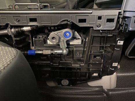
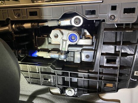
HIGH-LOW Range Adjustment (upper ball socket - red highlight below)

1. Remove the left Lower-Console Side Panel.
2. Release the Ball Socket from the Gear Selector Base.
3. Loosen the nut that attaches the Ball Socket to the Adjuster.
4. NOTE: It is recommended that you turn the Ball Socket one time and then do a test of the selector:
- If the HIGH gear does not engage correctly, turn the Ball Socket counter-clockwise.
- If the LOW gear does not engage correctly, turn the Ball Socket clockwise.
- Turn the Ball Socket as necessary.
5. Tighten the nut that attaches the Ball Socket to the Adjuster.
6. Install the Ball Socket to the Gear Selector Base.
7. Use the Transfer Box Selector to make sure that you can engage and disengage the High and Low-range gears.
8. Do steps 2 thru 7 again as necessary until the Transfer-Box Selector Cable is correctly adjusted.

Differential Lock Adjustment (lower ball socket - green highlight below)
9. Release the Ball Socket from the Gear Selector Base.
10. Loosen the nut that attaches the Ball Socket to the Adjuster.
11. NOTE: It is recommended that you turn the Ball Socket one time and then do a test of the selector.
Turn the Ball Socket as necessary.
12. Tighten the nut that attaches the Ball Socket to the Adjuster.
13. Install the Ball Socket to the Gear Selector Base.
14. Use the Transfer Box Selector to make sure that you can engage and disengage the Differential Lock.
15. Do steps 9 thru 14 again as necessary until the Transfer-Box Selector Cable is correctly adjusted.
16. Drive the vehicle a short distance and make sure that the Transfer Box Selector operates correctly.
17. Install the left Lower-Console Side Panel.

1773554687016.png


Trim Panels

4. Lower Console Left Side Panel


Remove
1. Remove the Upper-Console Lower Left Side-Panel.
2. Remove the two screws that attach the Side Panel to the Centre Console Armature.
3. Release the Side Panel from the 19 clips that attach it to the Lower Console Assembly.
4. Remove the Side Panel.
Forum Note: Use a flat trim tool to release the 19 clips. There is no need to remove the seat but it is helpful to move it back and forth as you work along the clips. The panel can be lifted up when fully released.

Install
5. Move the Side Panel into the correct position.
6. Install the Side Panel to the 19 clips that attach it to the Lower Console Assembly.
7. Install and tighten the two screws that attach the Side Panel to the Centre Console Armature.
8. Install the Upper-Console Lower Left Side-Panel.

2x screws here:
1773555117847.png


3. Upper Console Lower Left Panel

Remove
1. Remove the Knab Cover.
2. Remove the screw that attaches the Side Panel to the IP Carrier.
3. Release the Side Panel from the five clips that attach it to the Instrument-Panel Carrier.
4. Remove the Side Panel.

Install
5. Move the Side Panel into position.
6. Install the Side Panel to the five clips that attach it to the Instrument-Panel Carrier.
7. Install and tighten the screw that attaches the Side Panel to the Instrument-Panel Carrier.
8. Install the Knab Cover.

2. Knab Cover

Remove
1. Remove the Upper Console End Cap.
2. Remove the three screws that attaches the Knab Cover to the Instrument-Panel Carrier.
3. Release the Knab Cover from the four clips that attach it to the Upper-Console Lower Cover.
4. Disconnect the Electrical Connector from the Lamp.
5. Release the Harness from the clip that attaches it to the Knab Cover.
6. Remove the Knab Cover.

Install
7. Move the Knab Cover into position.
8. Install the Harness to the clip that attaches it to the Knab Cover.
9. Connect the Electrical Connector to the Lamp.
10. Install the Knab Cover to the four clips that attach it to the Upper-Console Lower Cover.
11. Install and tighten the three screws that attach the Knab Cover to the Instrument-Panel Carrier.
12. Install the Upper-Console End Cap

3x screws:
1773555989886.png


1. Upper-Console End Cap

Remove
1. Remove the Door Main Sealing.
Forum Note: You only need to pull a short section of the door seal away from the door frame adjacent to the end cap.
2. Release the End Cap from the six clips that attach it to the Instrument-Panel Carrier. (it's a tight fit!)
3. Remove the End Cap.
Forum Note: Pull the cap towards the seat. Keep it parallel to the side of the vehicle.

Install
4. Move the End Cap into position.
5. Install the End Cap to the six clips that attach it to the Instrument-Panel Carrier.
6. Install the Door Main Sealing.

1773556689345.png
 
Last edited:
My 2025 Trialmaster occasionally gives me - variously - a persistent or intermittent CDL lock error. The persistent error can always be rectified by shifting out of CDL and back in. This type of error only occurs about 1 out of 5 or 6 shifts. The intermittent error is quite odd: I'll shift into CDL locked and get a solid CDL lock indication on the telltale panel. Then, while backing up, I'll get a CDL lock error (flashing telltale) about 5 seconds after the intial successful lock indication. This error lasts about 2 or 3 flashes of the telltale then resolves itself.

I had already seen Dirtbox Overland's comments about the shift linkage, and for my vehicle, agree with him that something at the end of the CDL cable interferes with free motion of the cable as the ball joint moves aft. He removed the rubber/plastic boot. In my case, the adjuster barrel had been completey screwed in on the cable side (the left hand threads) by the factory and, in its aft-most position, the adjuster barrel was colliding hard against the rubber boot. And the ball joint threaded barrel end was bottomed out against the other end of the adjuster barrel (right hand threads). I removed about 2.5 mm from the ball joint threaded barrel - this let me unscrew the adjuster barrel one turn away from the cable end/rubber boot and gave me some room to adjust the ball joint farther aft. There's plenty of barrel left such that removing a few mm of barrel won't affect the integrity of the threaded portion. The alternative to what I did would be to adjust the cable at the transfer case end, but as far as I can tell, the cable ends are nearly inaccessible with the transfer case installed.

After shortening the ball joint threaded body, I adjusted the CDL lock linkage. The technique here is to shift into the desired position, unclip the ball joint from the ball stud, then adjust the cable so it sits on the ball with almost no tension fore or aft. This is the gross adjustment, one complete turn at a time of the ball joint. Once you're close, you can pop the ball joint back together, then use the barrel adjuster to make fine adjustments. Finish up by tightening the lock nut against the ball joint threaded body. You don't want excessive pressure on the cable at any particular shift position (the 4 combinations of Hi / Low / CDL) - too much presure will prematurely wear shift forks or slip rings in the transfer case. Each of the four possible selections of the transfer case will move the CDL cable very slightly compared to another selection - the critical selection I found was High / CDL unlocked: if I got that right, all the other positions seemed to work well.

My total adjustment was less than a full turn (by way of the adjuster barrel), and that seems to have resolved my intermittent CDL lock error problems. Or . . . the extensive shifting in and out of lock while testing my adjustments resolved whatever the problem was - perhaps a rough edge or swarf on some part that was worn off or knocked away with sufficient shifts. Although I seem to have eliminated the problem, I plan to change the transfer case fluid, and try to figure out how to drain the cooler as well, in case my theory about swarf is true. The three liters of Titan Sintopoid I ordered just arrived last night.

The ball joints used on the Grenadier are quite sloppy - there's probably about 0.03"/0.8mm of slop between the ball and socket. This isn't necessarily a problem. The transfer case has mechanical detents where the mechanism sits once a shift is complete. The shift cable just needs to move it there and - ideally, even necessarily - not put any force on the mechanism once the shift is complete. So as long as the cable gets the mechanism into its home, a little slop doesn't hurt anything. That said, I've sourced some precision Rose joints and associated parts to replace the OEM ball joints. I'll do a write-up of that once the parts arrive and are installed.

A couple notes about working with the ball joints might be handy for those who haven't dealt with them before. To remove the CDL ball joint, I used a square-shank screwdriver about 5/16" / 8mm across the flats, put it right next to the ball joint and against the bellcrank, then twisted the screwdriver to pop the ball joint off. It takes a fair amount of force - I put a small wrench on the screwdriver shank to help twist it. Be sure the lever you use is right next to the ball socket - too far away and you lose a lot of mechanical advantage and dramatically increase the force on all the associated parts. Another way - and very easy - is to use a thin-pattern 13 mm open end wrench: place the ball in the opening and pry away from the stud. The trick here is the wrench has to be just big enough to pass the ball as the socket slides off. To reinstall the ball joint, use a pair of slip-joint pliers to compress the ball back onto the stud. One end of the pliers goes on the ball socket and the other end goes on top of the bell crank - it's a long reach. Doing it this way avoids unecessary force on the bellcrank and puts all your effort into seating the ball joint.

Here's a pic of the CDL bellcrank:

bellcrank .jpg


A large aluminum gland nut secures the bell crank through the gray Delrin bushing on the left (24 mm nut). There's no need to remove the bellcrank to adjust the cables, but if you do, take care that the white PTFE bushing (not pictured) seats into the back of the bellcrank as you screw in the gland nut. The PTFE bush has a very thin wall projection that must seat into the bellcrank and you can easily crush it if it's not seated properly.

Here's a pic of the ball joint:

ball socket.jpg


The ball joint has flats for an 11 mm wrench (an odd size sometimes seen on brake bleeders) and the lock nut on the adjuster barrel threads takes a 13 mm wrench. More to come . . .

edit: added using 13 mm wrench to remove socket from ball
 
Last edited:
For the linkage pin possibly falling out, I've shared before that I purchased these size 14 silicon wedding bands that fit over the pin and looks pretty good.

 
After adjusting the OEM ball links at the shifter end of the transfer case cables and noticing a lot of play in the ball links, I decided to replace them with spherical rod end bearings. The goal was to reduce cable play and improve transfer case shifting. Here is a picture of the stock shifter and OEM ball links (LHD):

IMG_0471.jpg


Replacement of the OEM ball links involved measuring the existing ball joints so their geometry could be replicated, modifying new hardware, then installing and adjusting the rod end bearings and associated hardware. I used the following parts (part numbers are for McMaster-Carr):

Part #DescriptionNote
4483T42High-load ball joint rod endM8 × 1.25 mm internal thread, 36 mm joint centerline to rod end
91239A438M8 × 1.25 mm × 35 mm button head boltBlack oxide
91239A442M8 × 1.25 mm × 40 mm button head boltBlack oxide
95034A126Ball joint rod end insertCone style, 8 mm ID
93849A104M6 oversized washerStainless steel, 2.0–2.9 mm thick

Center Differential Lock

The center differential lock function uses a 90° bell crank outboard of the shifter. One arm engages a ball on the shift column via a loosely fitted blue plastic bushing; the other arm transmits motion through a ball joint and cable to the center differential lock in the transfer case. The ball joint centerline sits 13 mm above the bell crank arm mounting surface.

As supplied, the rod end measures 36 mm from joint centerline to the end of the threaded barrel. I reduced this to 28 mm, leaving approximately 16 mm of hollow barrel. Because the barrel threads did not run the full depth, I used a bottoming tap to extend the M8 × 1.25 mm threads to full depth. I reduced the height of the cone-style insert so the total stack - rod end plus cone - measured 13 mm from the bottom of the cone to the bearing centerline. A 35 mm bolt secures the assembly to the bell crank arm. Ineos applied thread locker to the OEM ball stud, so I chased the bell crank threads with a tap before installing the new bolt with medium-strength thread locker.

Here's a picture of the differrential lock parts stack:

IMG_0470.jpg


High/Low Shift

The High/Low shift function uses a ball link screwed into a threaded steel boss projecting from the outboard side of the shifter column, above the center differential lock bell crank. The joint centerline is 18 mm above the mounting plane. I used the same parts as the bell crank modification, but with different dimensions. The rod end was shortened by 2.5 mm to a centerline-to-barrel-end length of 33.5 mm. The cone was left as supplied and I added a thick-pattern washer beneath it to bring the stack to the required height of 18 mm. The spacer required is approximately 2.5 mm thick; I made it from a thick M6 washer drilled out to 8 mm and honed to the required thickness. Standard washers are typically about 1.5 mm thick, and the shifter geometry is such that stacking two of them would likely work equally well without adversely affecting cable alignment. The M8 × 1.25 mm × 40 mm button head bolt was shortened to 38 mm to maximize thread engagement in the threaded steel boss on the shifter column without bottoming out - approximately 16 mm of thread projects beyond the parts stack. As before, Ineos used a lot of thread locker on the OEM ball stud; I chased the threads with a tap, then installed the parts with medium-strength thread locker.

Here is a picture of the High/Low parts stack:

IMG_0474.jpg


Here is a picture of the installed spherical rod bearings. Despite being larger than the OEM parts, there is plenty of clearance around the new rod bearings in all four positions.

IMG_0477.jpg


Bell Crank Endplay

The last modification I made was to reduce the endplay beneath the 24 mm gland nut that secures the differential lock bell crank. Using feeler gauges, I measured 0.013"/0.33 mm of play between the gland nut and the Delrin bushing it bears against. I faced the small end of the gland nut, removing 0.010" of material and leaving 0.003"/0.08 mm of clearance beneath the head. After reinstalling the nut, I confirmed 0.003" of clearance with a feeler gauge to verify the mechanism was not binding. This modification eliminated a significant amount of wasted motion in the linkage.

Conclusions

The spherical rod end bearings reduce play throughout the system, but I'm not convinced this really resulted in a noticeable difference in shifting feel. Transfer case shifting involves selecting a position like High/Lock, then finding the detent for the pin lock operated by the shift collar. The shifter allows some overshoot past the final position - you then walk it back until the lock pin drops into place. That technique masks cable slop in a way that manual transmission shifting does not, where slop is immediately noticeable and can be obnoxious. By comparison, eliminating nearly all the endplay under the bell crank gland nut had a clear, immediate effect - the shifter feels more precise.
 

Attachments

  • IMG_0471.jpg
    IMG_0471.jpg
    210.6 KB · Views: 0
  • IMG_0477.jpg
    IMG_0477.jpg
    257.8 KB · Views: 0
Last edited:
Back
Top Bottom