A community driving the extraordinary.
Welcome to Global Grenadiers — the worldwide community for INEOS Grenadier and Quartermaster owners and enthusiasts. Register free to join the conversation. Share your build and adventures, access technical guides, join your regional social group, get help on the trail, and receive our monthly newsletter.
INEOS Agents, Dealers or Commercial vendors — please use the Contact us link at the bottom of the page.
One thing to note, even in a non-N1 those rear bolts are PITA and blocked from large tool access due to the brace/cross bracket of the rear seat structure. The trick is a 90º Torx key or a wobble bitOne issue...to remove the remaining back trim panels means removing the M10 bolts (seems unsuitably large for a trim retaining fastener?) indicated here. However, some are located under the rear seat base and are not accessible in an N1. Clearly if the seat base was 70mm to the rear then these bolts would be directly accessible.
Thanks ~ I'm at the agents later this week and want to check out the M1s on this matter. If access is reasonable, it adds another reason to move the seats back.One thing to note, even in a non-N1 those rear bolts are PITA and blocked from large tool access due to the brace/cross bracket of the rear seat structure. The trick is a 90º Torx key or a wobble bit
I'm struggling to understand why they are M10 though?

100% I don't see why that wouldn't workIt may rattle a bit, but a layer of foam or foam pads could stop that.
Managed to find an M1 to compare access to the rear M10 bolts:Thanks ~ I'm at the agents later this week and want to check out the M1s on this matter. If access is reasonable, it adds another reason to move the seats back.
I'm struggling to understand why they are M10 though?

I ended up getting this set:One thing to note, even in a non-N1 those rear bolts are PITA and blocked from large tool access due to the brace/cross bracket of the rear seat structure. The trick is a 90º Torx key or a wobble bit
So so you think that your wiring set up is the same as all others as I have the dual battery , high load and auxiliary socket set up, but at one point you thought maybe your vehicle was wired differently although that was before you could get full access to your battery box.So with decent access at last, it's easier to trace most of the key wiring.
Auxiliary battery positive:
View attachment 7821290View attachment 7821291
Into the Littelfuse inline fusebox
View attachment 7821293View attachment 7821295
and fused at 300A:
View attachment 7821296
and running into the Smartpass service battery outlet:
View attachment 7821297
I'm not sure this is that clear, but my workings on how the main and auxiliary battery are wired into the Smartpass (blue line), 350A supply for the rear NATO socket (green line) & 80A supply to the auxiliary fusebox (green line). The latter being more of a guess as the cable is bound into the loom and so not possible to trace 100%:
View attachment 7821298
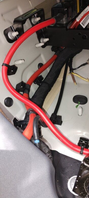
The other main positive supply coming off the main battery is sheathed in black convoluted tube in some of the photos and disappears down the right hand side of the gearbox tunnel heading for the engine bay. It does not appear to be fused in the immediate vicinity.
Yes I have the same connectors and have optioned dual battery , high load /winch , auxiliary sockets etc.Great job. Does everyone have two mystery connectors just flapping in the breeze either side of the CTEK? I have them - wrapped in spongy foam stuff it seems - like small molex in fact I see one in your picture here just to the right of the obvious INEOS sticker: Maybe as I have a basic model it's powering something I don't have!!
https://www.theineosforum.com/attachments/img_20230726_112124692-jpg.7821295/
I think they connect to the seat belts and are supposed to alarm if disconnected whilst moving.Great job. Does everyone have two mystery connectors just flapping in the breeze either side of the CTEK? I have them - wrapped in spongy foam stuff it seems - like small molex in fact I see one in your picture here just to the right of the obvious INEOS sticker: Maybe as I have a basic model it's powering something I don't have!!
https://www.theineosforum.com/attachments/img_20230726_112124692-jpg.7821295/


")