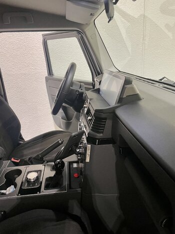
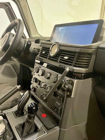
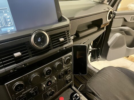
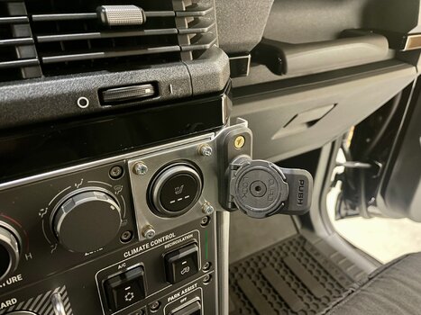
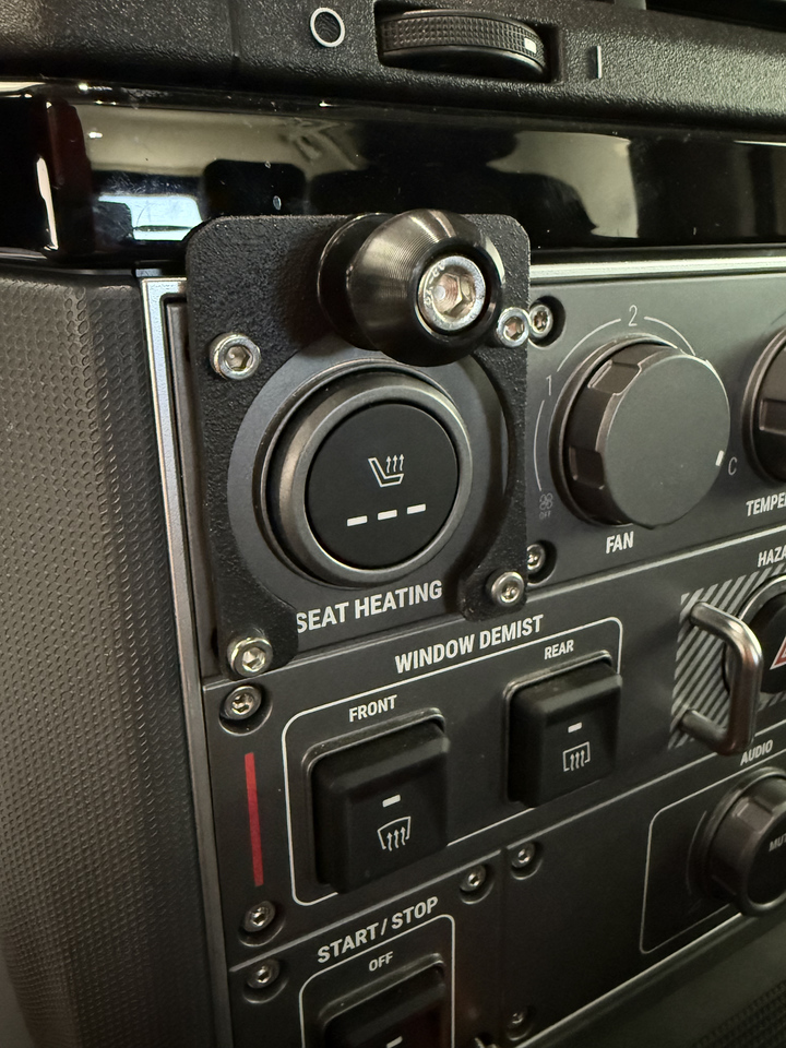
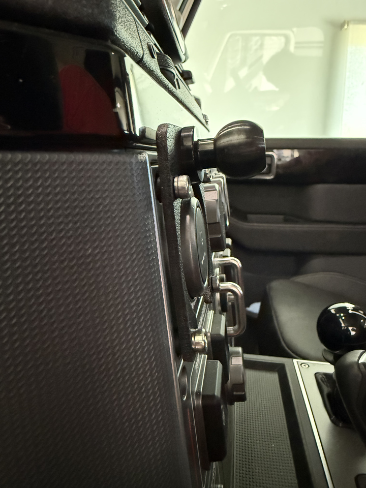
This is my mount, is from agile off-road. Really happy with it.

Bullet point ultra short Arm + cradle.

Bullet point ultra short Arm + cradle.
A community driving the extraordinary.
Welcome to Global Grenadiers — the worldwide community for INEOS Grenadier and Quartermaster owners and enthusiasts. Register free to join the conversation. Share your build and adventures, access technical guides, join your regional social group, get help on the trail, and receive our monthly newsletter.
INEOS Agents, Dealers or Commercial vendors — please use the Contact us link at the bottom of the page.
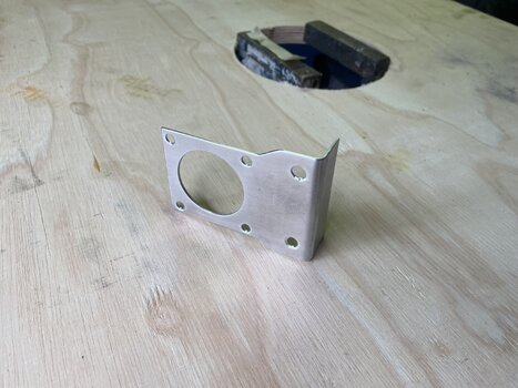
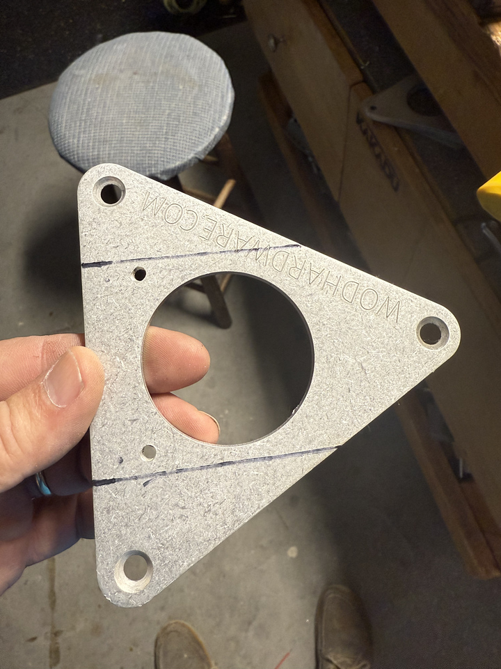
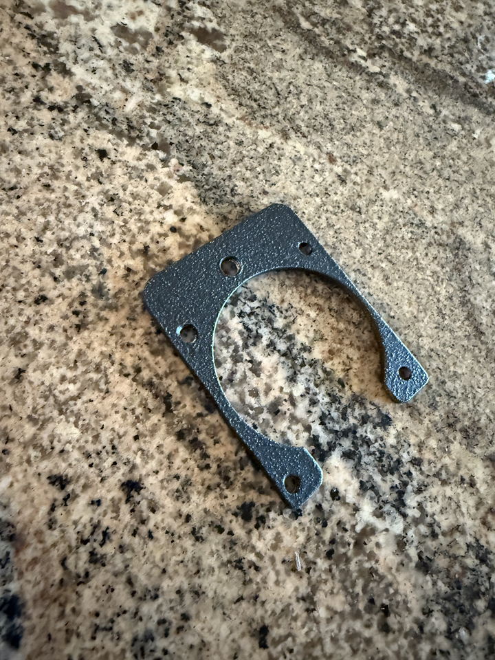


") It took me a lot longer to draw the stuff in Fusion (free version) than it did to print them. It's a pretty steep learning curve.
It took me a lot longer to draw the stuff in Fusion (free version) than it did to print them. It's a pretty steep learning curve.