Hi All,
I have the factory dual battery setup and decided to make a few changes to the vehicle wiring to make it more useful. I wanted to have the following:
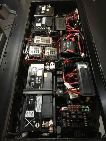
I rewired the second (5 way) high current fuse box to be powered from the second battery instead of the main battery - this moved the power supply for the NATO socket and grey aux relay / fuse box to the second battery.
I rewired to input to the CTEK unit to come from the main (7 way) high current fuse box.
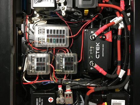
I added a small aux fuse box powered from the 5 way high current fuse box.
I rewired the power supply to the RI03 relay so that it comes from my new aux fuse box instead of from FI04 - this is the red wire going into the interior electrical centre fuse box wher a fuse used to go. This powers the front and rear 12V outlets, read USB outlets, front footwell outlets and EXT1 under bonnet outlet and the lights in the aux switches of the roof console.
I cut the wire from the EXT5 relay output under the grey fuse / relay box and wired it directly to the positive coil connection of the Albright relay - the NATO socket is now under control of the EXT5 switch. I need to replace the fuse on this with a 5A one.
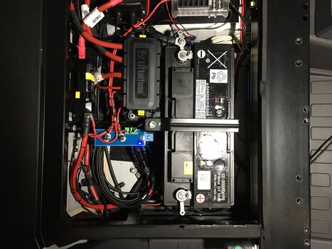
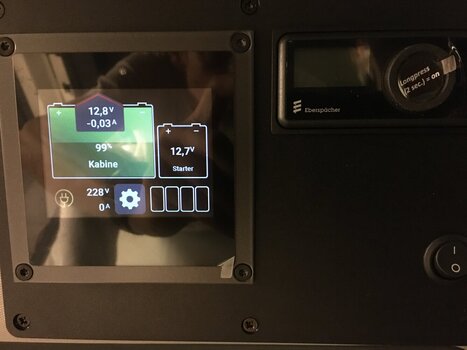
I added a Victron Smart Shunt battery monitor to the ground line from the second battery - I can now precicely monitor its state of charge.
I removed the 300A single fuse between CTEK output and second battery and used a 300A Z Case fuse in the 5 way high current fuse box instead.
I added additional lighting in the rear load space and am output for a fridge from the new aux fuse box.
I also got rid of the top panels of the under seat electrical enclosure and secured the front panesls with cable ties - the whole under seat enclosure is a crap design which would get any of my engineers fired.


Tristan
I have the factory dual battery setup and decided to make a few changes to the vehicle wiring to make it more useful. I wanted to have the following:
- Front and rear 12V outlets powered from second battery
- Rear USB outpets powered from second battery
- All aux power supplies (under bonnet, roof and footwell) powered from second battery
- Rear high power output (NATO socket) powered from second battery and switchable whenever needed (no neutral interlock etc.)
- Winch (transmission) still protected by existing interlocks
- Aux fusebox for additional 12V loads on second battery
- Battery monitoring on second battery
- Allow for high current supply to inverter from seconf battery
I rewired the second (5 way) high current fuse box to be powered from the second battery instead of the main battery - this moved the power supply for the NATO socket and grey aux relay / fuse box to the second battery.
I rewired to input to the CTEK unit to come from the main (7 way) high current fuse box.
I added a small aux fuse box powered from the 5 way high current fuse box.
I rewired the power supply to the RI03 relay so that it comes from my new aux fuse box instead of from FI04 - this is the red wire going into the interior electrical centre fuse box wher a fuse used to go. This powers the front and rear 12V outlets, read USB outlets, front footwell outlets and EXT1 under bonnet outlet and the lights in the aux switches of the roof console.
I cut the wire from the EXT5 relay output under the grey fuse / relay box and wired it directly to the positive coil connection of the Albright relay - the NATO socket is now under control of the EXT5 switch. I need to replace the fuse on this with a 5A one.
I added a Victron Smart Shunt battery monitor to the ground line from the second battery - I can now precicely monitor its state of charge.
I removed the 300A single fuse between CTEK output and second battery and used a 300A Z Case fuse in the 5 way high current fuse box instead.
I added additional lighting in the rear load space and am output for a fridge from the new aux fuse box.
I also got rid of the top panels of the under seat electrical enclosure and secured the front panesls with cable ties - the whole under seat enclosure is a crap design which would get any of my engineers fired.
Tristan

") ... a truly professional approach to achieve how most expect it should have been done in the first place!
... a truly professional approach to achieve how most expect it should have been done in the first place!