- Local time
- 6:55 AM
- Joined
- Jun 29, 2022
- Messages
- 467
Hello team ,
So here it goes , the usual disclaimer, repeat the below at your own risk .
Ever since day 1 I needed a set of drawers for the back of the gren to store all my stuff .
In the beginning i started planning and designing custom drawers for it ….. then life got in the way …
So i begun looking around . I settled on the buzz overland drawers . Overall no complaints , solid built , they dont squeak or creak and can carry decent amount of weight .
Downside was the there were no locks on the drawers and i had to remove the L track and install the Buzz overland floor . But now that its done not a big deal .
So here it goes .
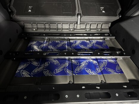
First removal of the rear L track was easy along with installation of some dynamat since i was there.

Then while installing the floor attachments ( Buzz overland has a great video that walk you through step by step ) i discovered that my truck must have been a Friday afternoon one . Since one of the bolts was cross threaded. Thankfully the empire of dirt provided a tap to chase the threads . No big deal .

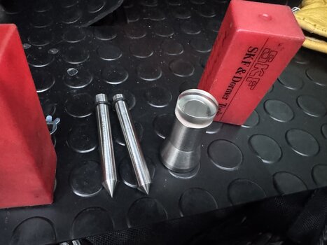
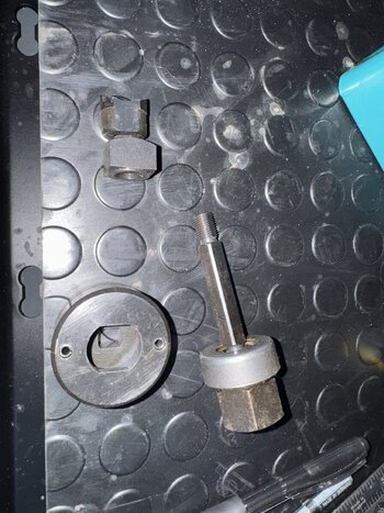
To align the cross members with the floor attachments you need something conical to align the holes . I used a hose removal tool .

Once that is done then everything is tightened and torqued . That is the floor structure prepared .

Over this goes the floor . And on the floor the drawers . Drawers can be removed and the floor used as normal .
Now the issue is came across is that since i have the inverter my 12v plug is lower down . This interferes with the drawer top plate .
So some swearing and fiddling about i managed to remove it with out taking everything out .

Then i used a step bit to move the hole higher . After that everything worked great . Used a plastic plug to cover the old hole .

And that is it for the install . Done the whole thing in a single evening. Can be done solo .
So here it goes , the usual disclaimer, repeat the below at your own risk .
Ever since day 1 I needed a set of drawers for the back of the gren to store all my stuff .
In the beginning i started planning and designing custom drawers for it ….. then life got in the way …
So i begun looking around . I settled on the buzz overland drawers . Overall no complaints , solid built , they dont squeak or creak and can carry decent amount of weight .
Downside was the there were no locks on the drawers and i had to remove the L track and install the Buzz overland floor . But now that its done not a big deal .
So here it goes .
First removal of the rear L track was easy along with installation of some dynamat since i was there.
Then while installing the floor attachments ( Buzz overland has a great video that walk you through step by step ) i discovered that my truck must have been a Friday afternoon one . Since one of the bolts was cross threaded. Thankfully the empire of dirt provided a tap to chase the threads . No big deal .
To align the cross members with the floor attachments you need something conical to align the holes . I used a hose removal tool .
Once that is done then everything is tightened and torqued . That is the floor structure prepared .
Over this goes the floor . And on the floor the drawers . Drawers can be removed and the floor used as normal .
Now the issue is came across is that since i have the inverter my 12v plug is lower down . This interferes with the drawer top plate .
So some swearing and fiddling about i managed to remove it with out taking everything out .
Then i used a step bit to move the hole higher . After that everything worked great . Used a plastic plug to cover the old hole .
And that is it for the install . Done the whole thing in a single evening. Can be done solo .