I just wanted creat a post where one does not have to weed through it to find what is needed.
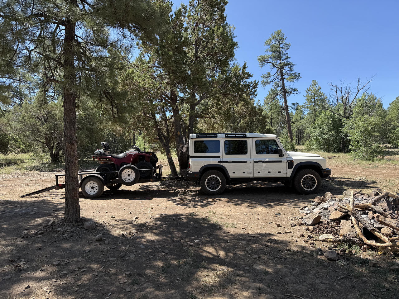
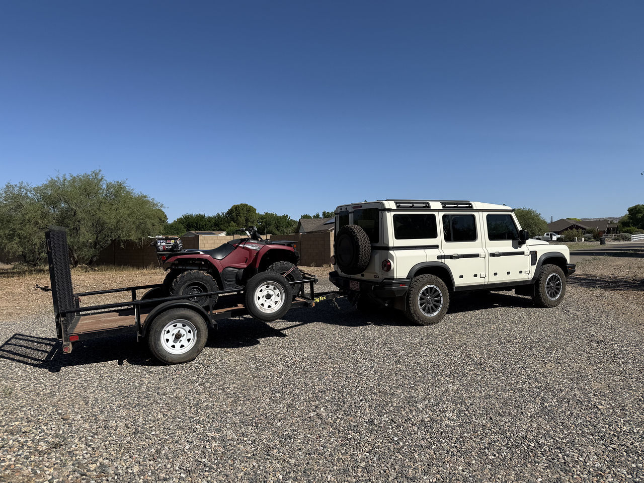
Hitch: CATuned
 catunedoffroad.com

Wire module : Amazon.de : CURT 59187 Powered 3-to-2-Wire Splice-in Trailer Tail Light Converter Kit, 4-Pin Wiring Harness
Step 1.
Adding the hitch? remove the cover plate and bolt on with the provided Red Locktite. (Factory nuts are welded to the frame)
Step 2.
Wiring note 1:
YOU ONLY NEED 3 wires, NOT 4. Left blinker, right blinker and running signal - do not connect the Brake light Connection. It will not work!
Why? The Blinker light on our truck and the stop light are the same light. (unlike some foreign cars, there the blinker and the stop are two different lights)
Wiring note 2:
First, I would like to point out, with any new car or truck, always use a powered converter module (isolation module).
The modern cars and trucks of today have CAN bus systems, and the tiny wires are not designed to carry any extra load on the light circuits. Also trailer you intend to pull may have old-school incandescent bulbs that draw lots of power. And if you pull a boat, the lights are easily shorted to DC - (ground),
Wiring Step 3:
My wiring where in tied in upstream of the trailer module.
Right turn -Green / brown stripe (correct!)
Left Turn -Yellow / Gray stripe (correct!)
Brake - DO NOT CONNECT TO MODULE
Tail - Green / purple (correct!)
How to remove the right side panel.... I did not have to remove the nut inside the box...
Video link removal of right panel
How the panel installs into the truck
Video link right panel clips
Video link more details of how the side panel clips it...
Here I used posi-tap... Throw those blue things in the garbage! Note: I show 4 here, you only need 3 (brake is not needed, do not connect or it will not work)


Here, I used a piece of plastic tubing (like fish tape)to run the wire through the inner wall grommet hole.

Here you can see the plastic hose...

Here you can see the wire taped to be pulled into the truck (I had the cut the trailer wire to get it through the hole)

Here you can see the wires pulled through the rubber grommet.

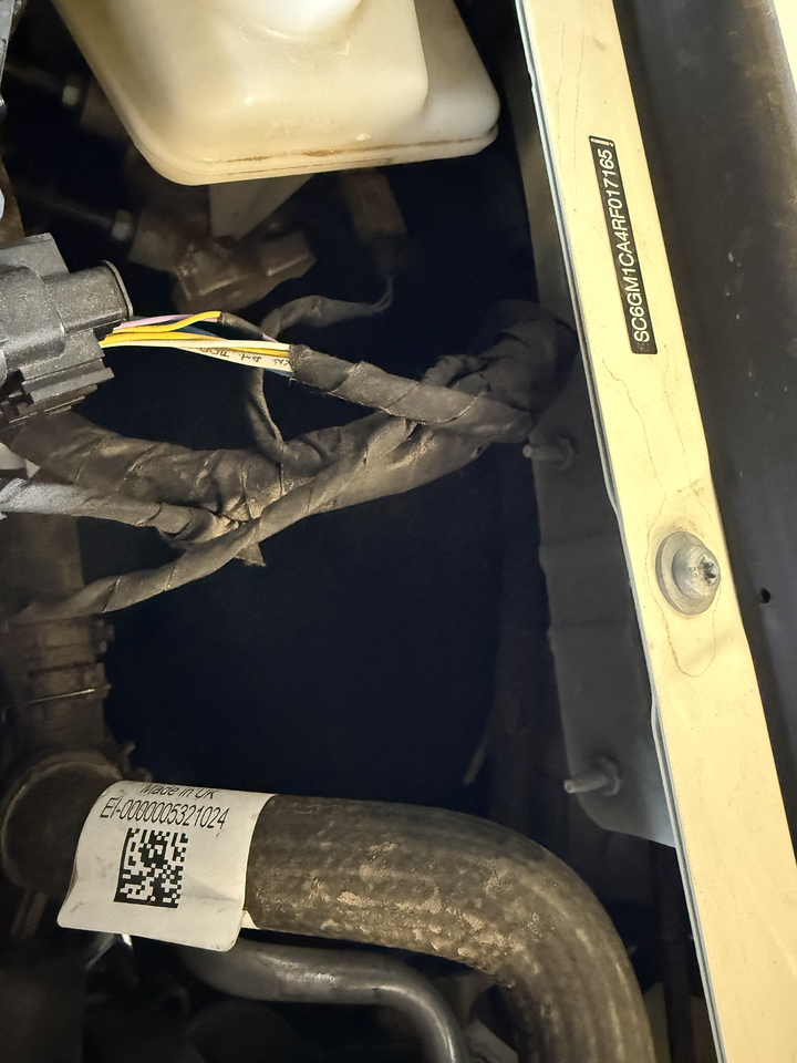
Wiring note 4: Powering up the module
I wired the trailer module to the power port provided under the hood on the driver's side, taped to the main wiring harness. Look for two wires with clear heat shrink on them (halfway between the firewall and the radiator). There is a felt wheel liner is sits against. Put a heat shield (metal or wood) to protect the felt and use a heat gun to remove the heat shrink with hot glue. (I used a needle nose to gently pull on the heat shrink as I heated - It takes a lot of heat to get the glue to melt, and the wires are very short)
Power wires under the hood!!!
Hitch: CATuned
Ineos Grenadier Rear 2" Hitch Receiver
Upgrade your Ineos Grenadier's towing capability with our Rear 2" Hitch Receiver, designed to seamlessly integrate with your existing rear bumper. Crafted from 3/8" steel, this hitch receiver provides maximum strength and durability for your off-road adventures. It includes all the necessary...
Wire module : Amazon.de : CURT 59187 Powered 3-to-2-Wire Splice-in Trailer Tail Light Converter Kit, 4-Pin Wiring Harness
Step 1.
Adding the hitch? remove the cover plate and bolt on with the provided Red Locktite. (Factory nuts are welded to the frame)
Step 2.
Wiring note 1:
YOU ONLY NEED 3 wires, NOT 4. Left blinker, right blinker and running signal - do not connect the Brake light Connection. It will not work!
Why? The Blinker light on our truck and the stop light are the same light. (unlike some foreign cars, there the blinker and the stop are two different lights)
Wiring note 2:
First, I would like to point out, with any new car or truck, always use a powered converter module (isolation module).
The modern cars and trucks of today have CAN bus systems, and the tiny wires are not designed to carry any extra load on the light circuits. Also trailer you intend to pull may have old-school incandescent bulbs that draw lots of power. And if you pull a boat, the lights are easily shorted to DC - (ground),
Wiring Step 3:
My wiring where in tied in upstream of the trailer module.
Right turn -Green / brown stripe (correct!)
Left Turn -Yellow / Gray stripe (correct!)
Brake - DO NOT CONNECT TO MODULE
Tail - Green / purple (correct!)
How to remove the right side panel.... I did not have to remove the nut inside the box...
Video link removal of right panel
How the panel installs into the truck
Video link right panel clips
Video link more details of how the side panel clips it...
Here I used posi-tap... Throw those blue things in the garbage! Note: I show 4 here, you only need 3 (brake is not needed, do not connect or it will not work)
Here, I used a piece of plastic tubing (like fish tape)to run the wire through the inner wall grommet hole.
Here you can see the plastic hose...
Here you can see the wire taped to be pulled into the truck (I had the cut the trailer wire to get it through the hole)
Here you can see the wires pulled through the rubber grommet.
Wiring note 4: Powering up the module
I wired the trailer module to the power port provided under the hood on the driver's side, taped to the main wiring harness. Look for two wires with clear heat shrink on them (halfway between the firewall and the radiator). There is a felt wheel liner is sits against. Put a heat shield (metal or wood) to protect the felt and use a heat gun to remove the heat shrink with hot glue. (I used a needle nose to gently pull on the heat shrink as I heated - It takes a lot of heat to get the glue to melt, and the wires are very short)
Power wires under the hood!!!
Last edited: