
- Local time
- 11:37 AM
- Joined
- Jun 29, 2022
- Messages
- 484
Ok guys here it goes.
Usual disclaimer, I did this myself , I am happy to accept the risks.
If you copy anything you do so in your own risk. If you injure yourself or burn your car down is your fault.
With that out of the way, let’s get down to business. I wanted a light bar for the car.
As always, I wanted this to be as reversible as possible, so cutting wiring harnesses was simply not an option for me.
I wanted the light bar to be connected to EXT5 and to turn on with high beams.
So, I ordered and owl van Lazer 18 elite light bar to install on the grenadier.
The placement of it was out of the way as much as possible did not interfere with airflow of the radiator and it only needed some trimming of the plastic mesh leaf protector (at least that is what I think it is, replacement ordered from the dealer anyway just in case I want to remove the lightbar and put everything back as it was.)
Mounting I used the OWL mounts simply because there is no way I would have enough time to do the wiring, mounting and brackets. Ordering from the states plus the import taxes it was only 50 GBP more than buying straight from the UK, and I got the brackets that saved me at least one hour.
Now the lightbar comes with its own wiring harness, but it’s a huge and bulky thing, I hate extra wires and untidiness.
So, I decided to do my one wiring harness. (that was type 2 fun in the cold). Anyway.
Step 1: Disassembly
You will essentially need only torx for this. Take your time and make sure you do not loose any screws.
First thing to remove is the light shrouds and light surrounds.
Once that is done you have to remove the weather stripping from the front grill, use a panel tool with some tape on it (I scratched my grill, yes, I am annoyed). if the seal comes up without the clip get some needle nose pliers, grasp the clip and apply Constan pressure upwards, it will come out.
To get the bottom 2 screws of the grill you will need to drop the centre section of the bumper.
Once that is done the grill will come off.
OWL have a very nice video of the disassembly . Linked below :
View: https://www.youtube.com/watch?v=8nOHwviTq84
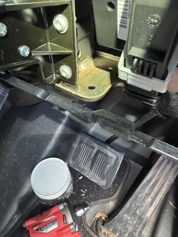
Step 2: Light bar install.
I used the included brackets and cut the honeycomb mesh as shown in the picture.
I used 2x zip ties to attach the bottom end of my box cut to the ‘V’ metal behind so it does not flop around.
Made sure the light bar was level.


Removing the ambient air sensor is the best way to be able to tighten the screws of the lightbar .
Usual disclaimer, I did this myself , I am happy to accept the risks.
If you copy anything you do so in your own risk. If you injure yourself or burn your car down is your fault.
With that out of the way, let’s get down to business. I wanted a light bar for the car.
As always, I wanted this to be as reversible as possible, so cutting wiring harnesses was simply not an option for me.
I wanted the light bar to be connected to EXT5 and to turn on with high beams.
So, I ordered and owl van Lazer 18 elite light bar to install on the grenadier.
The placement of it was out of the way as much as possible did not interfere with airflow of the radiator and it only needed some trimming of the plastic mesh leaf protector (at least that is what I think it is, replacement ordered from the dealer anyway just in case I want to remove the lightbar and put everything back as it was.)
Mounting I used the OWL mounts simply because there is no way I would have enough time to do the wiring, mounting and brackets. Ordering from the states plus the import taxes it was only 50 GBP more than buying straight from the UK, and I got the brackets that saved me at least one hour.
Now the lightbar comes with its own wiring harness, but it’s a huge and bulky thing, I hate extra wires and untidiness.
So, I decided to do my one wiring harness. (that was type 2 fun in the cold). Anyway.
Step 1: Disassembly
You will essentially need only torx for this. Take your time and make sure you do not loose any screws.
First thing to remove is the light shrouds and light surrounds.
Once that is done you have to remove the weather stripping from the front grill, use a panel tool with some tape on it (I scratched my grill, yes, I am annoyed). if the seal comes up without the clip get some needle nose pliers, grasp the clip and apply Constan pressure upwards, it will come out.
To get the bottom 2 screws of the grill you will need to drop the centre section of the bumper.
Once that is done the grill will come off.
OWL have a very nice video of the disassembly . Linked below :
View: https://www.youtube.com/watch?v=8nOHwviTq84
Step 2: Light bar install.
I used the included brackets and cut the honeycomb mesh as shown in the picture.
I used 2x zip ties to attach the bottom end of my box cut to the ‘V’ metal behind so it does not flop around.
Made sure the light bar was level.
Removing the ambient air sensor is the best way to be able to tighten the screws of the lightbar .


 absolutely insane install.. that is how it’s done
