OK so I did the install today. Here are some photos and some details that people might find useful.
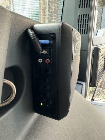
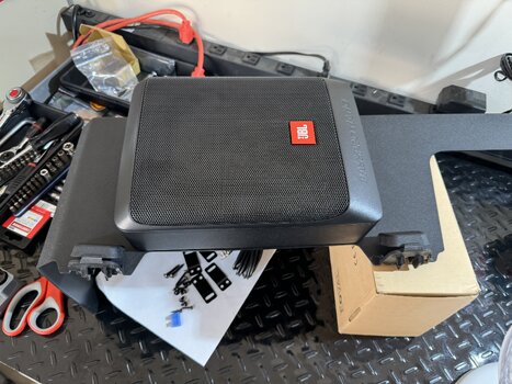
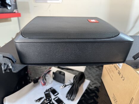
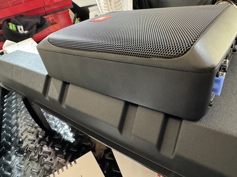
First, it is a great quality sub and is solid metal. The base is a heatsink so that also made me consider where to mount it to allow some heat dissipation.
I considered under the passenger seat but to do that well would mean moving the seat and making something to mount it with.
I scratched the idea of mounting on the outside of the plastic trim in the rear passenger footwell. Mainly as the plastic is flimsy and the unit heavy and bass causes rattles. It also would be a real fudge to stop it fouling the floor mats and it would get kick by kids (I don't have any young ones) and others. It may also have got wet and dirt kicked at it.
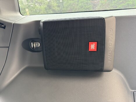
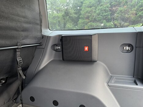
In the end I went with the rear install. Let me say it sounds amazing! Great sub and gives the audio system all the missing kick that was missing.
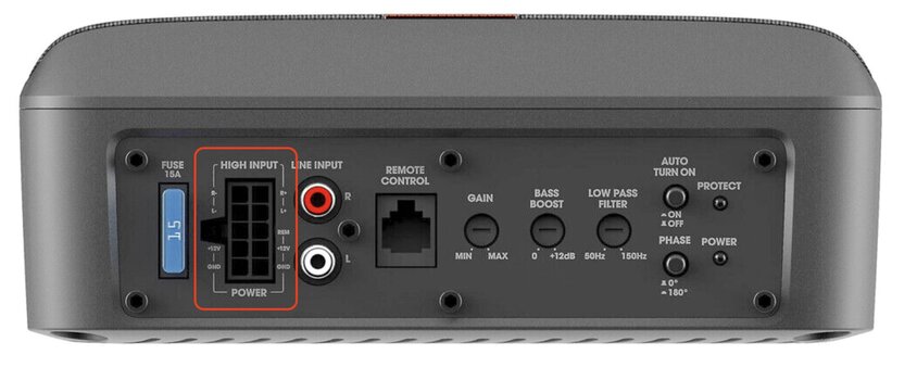
Also, the stock harness is so short that installing it anywhere means extending it, so I just thought 3 meters is as easy as 6 inches (confusing isn't it) so I just went for the best option in my opinion.
The sub was $185 from an eBay seller, and arrived as new perfect stock.
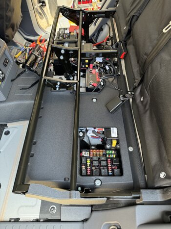
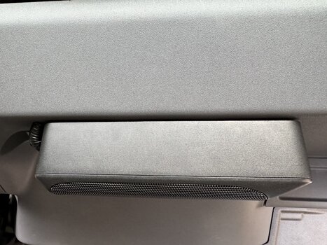
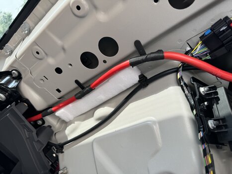
The side panel is a beast to get out, but it is all pop off connectors. I also added some foam (cut from the sub packaging) behind in two places just to give some sound baffling and anti vibration. The panel has some attached but it's super thin. This panel is also very solid and is fitted very tight and buts up against the metalwork under the rear window. All this means I have no vibration or reverberation other than that expected and desired.
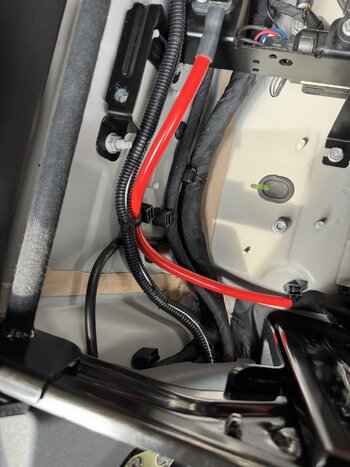
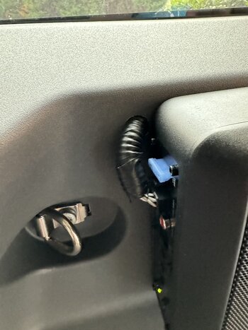
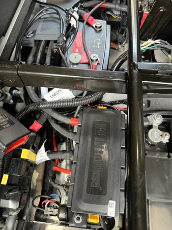
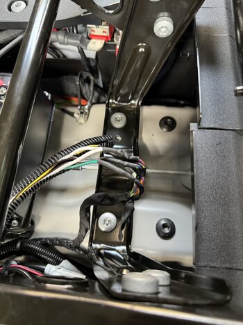
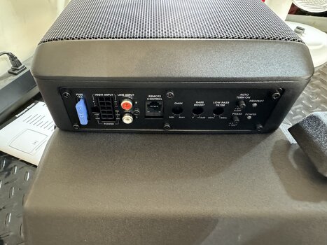
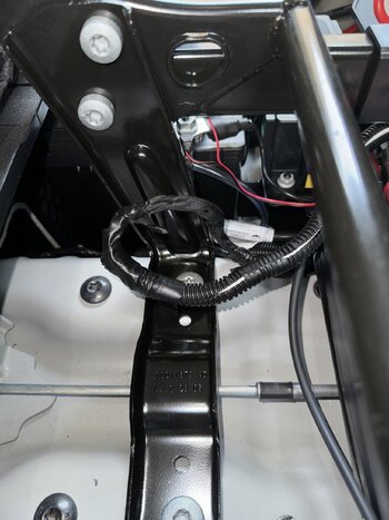
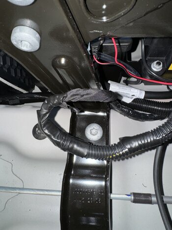
I used the JBL supplied connector and short wiring harness. Note: Ineos have 8 wires in their harness. JBL combined the pos and neg leads using a 2 into 1 splice. This meant I only had to run a 6 core loom/harness to the rear. I simply twisted the Ineos wires together and soldered them to the new harness I made. Yes, I did finish it all off with conduit cover and tape. It is now all tucked away and safe and neat. Soldered spliced connections, heat shrunk, plastic cover (flexible split conduit), and then taped to prevent it coming apart.
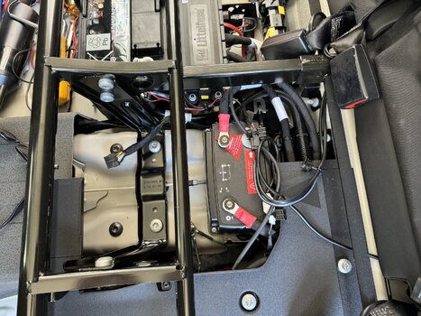
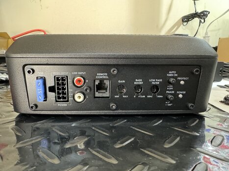
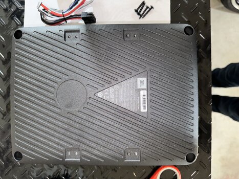
I added some pics on the bench when seeing how it might mount on the plastic battery compartment cover. It gives you some visuals of the unit.
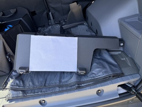
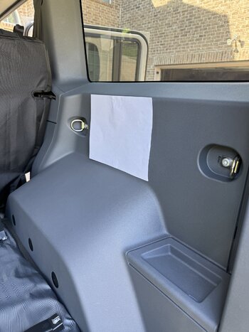
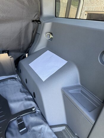
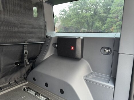
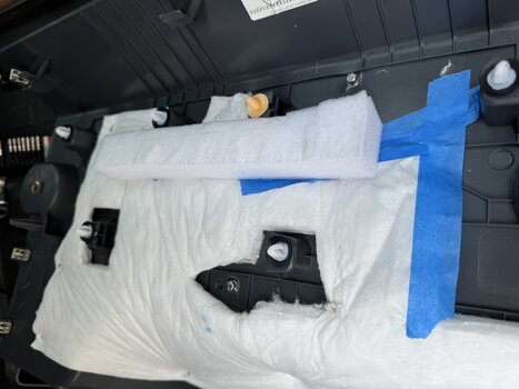
Then the location where it went. Once removed I made a paper template and drilled 4 holes to mount the sub. It uses 4mm metric threaded screws. I used some small bolts with washers and locking washers. I also added blue thread lock to prevent anything shaking loose just in case.
You will see an image with some blue painters tape. That was just to hold the factory noise insulation in place as this was disturbed when I drilled holes. You will also see the added foam from the sub packaging materials. This stops the plastic rattling, assuming it would have anyway.
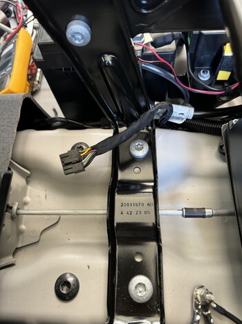
The image with the panel removed also shows the other bit of foam I added. Note, I also removed the B pillar trim where the seatbelt goes through, and loosened the trim on the B pillar that is next to the seat. I didn't take a photo that but I needed to do that to thread the wiring harness I made. It's all pretty intuitive.
The rest are images of the cable run and splice and the final result. Very impressive sound. Very clean install and probably the best worst location. Unless you need all the space for serious overloading then this will work. If you're going serious overloading then a sub ain't a priority

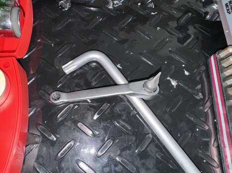
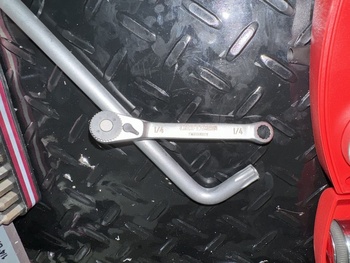
Now, dealing with those Torx 50 screws. I have an Allen style wrench but even that's a PITA. I have a T50 bit but only a Snap-On bit fits as others are too think on the spines. I found a flat blade 5/16" (about 8mm) bit also fits! Then I have a mini craftsman wrench for screwdriver bits. That is a game changer. Get one here
Amazon Link.
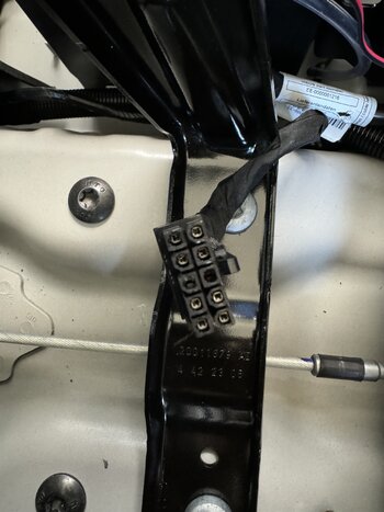
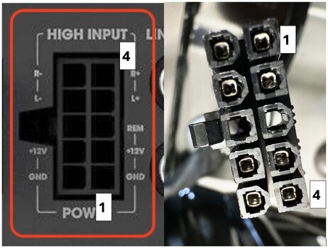
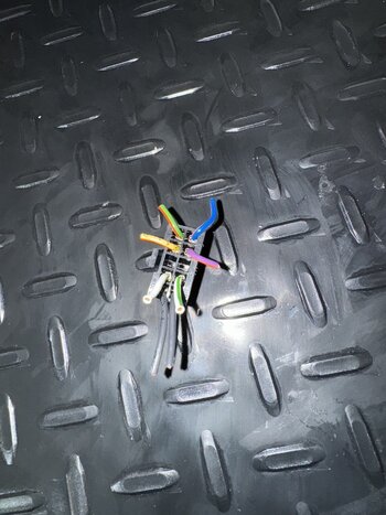
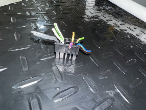
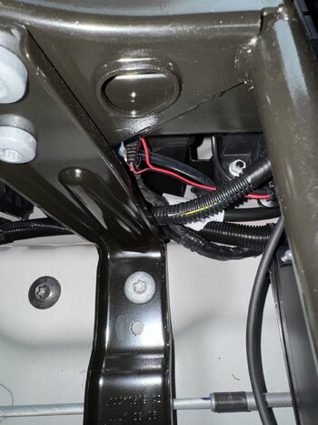
I also left you a photo of the now removed factory connector that is useful as a color code if you ever mess up.
Any questions ask away.
Did I mention it sounds awesome and is the missing oomph for the factory setup.


 Nice write-up, thanks for documenting the leg work!
") And it also included time to pop to O'Relliy's and be charged excessive amounts of money for some wire/cable to make up the harness
And it also included time to pop to O'Relliy's and be charged excessive amounts of money for some wire/cable to make up the harness