The Grenadier Forum
Register a free account today to become a member! Once signed in, you'll be able to contribute to the community by adding your own topics, posts, and connect with other members through your own private inbox! INEOS Agents, Dealers or Commercial vendors please use the contact us link at the bottom of the page.
-
Guest submit your best shot for a chance to win the December Photo Contest. Photo Contest Click Here
You are using an out of date browser. It may not display this or other websites correctly.
You should upgrade or use an alternative browser.
You should upgrade or use an alternative browser.
12 screws, still won't come down
- Thread starter scotchjeff
- Start date
There are clips holding the panel in place still. Use a plastic pry bar to lever the panel off or your fingers to gently pry the panel off. You'll then see the two screws you need to remove to drop the inner panel and expose the wiring.
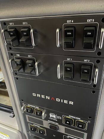
On my Grenadier there is no need to remove screws, they are for looks only, nothing more. I use a trim bar or my finger to grab a corner and work it across they pull down on everything. I have taken my overhead down several times. I ordered the overhead in Black stainless, however it only has one row of switches. I need two rows. RockFoxx.com is working on that.I am trying to pull down the overhead panel in the pic...there are 12 screws that i removed, but something is still holding the panel to the ceiling of the Grenadier.
See pic...what else do i need to do?
I thought those used adhesive to glue it on top of the existing plate.On my Grenadier there is no need to remove screws, they are for looks only, nothing more. I use a trim bar or my finger to grab a corner and work it across they pull down on everything. I have taken my overhead down several times. I ordered the overhead in Black stainless, however it only has one row of switches. I need two rows. RockFoxx.com is working on that.
No glue, two longer identical screws, it is very decent quality. Better than the net in the G550.I thought those used adhesive to glue it on top of the existing plate.
So are there any screws needed to be removed or not?
Not on mine, I removed them once and realized these screws are for looks. They are fake. When you look on the inside, you see the screws go nowhere. Use a pry bar at the end towards the 2nd. row, pop it out and everything will follow. I use a cardboard box on the lip of the info-screen to help secure the control panel its long and I don't want it hanging by wires. When I get my stuff from RockFoxx I'll take photos and post them.So are there any screws needed to be removed or not?
I tried it myself just some minutes ago. I couldn't manage to pull the panel down. The clips in the middle went loose, but I couldn't get the rear end loose. Maybe I wasn't brave enough to pull hard. Is the a trick?
You will need to remove all screws and the facia comes off. Then there should be two black screws towards rear of car. After removing them you should be able to pull the panel downwards from the upper/rear car side. Towards the mirror is a kind of hinge. Do not pull there.
Don’t pull on panel!! Remove back screwed X8 4 on each side starting at back. Then remove the grey plastic that covers the switches either one row or tow depending on how you ordered. Under that grey cover is 2 screws at the back. Take those out and it will hinge forward! The grey plastic is held in by clips down the middle, be gentle or you’ll bend it and leave damage. Use a plastic pry tool down the middle moving back to front.
OK. Having followed advice as provided above I have come to the point where Island Falconer warns of being very careful. Currently I have chickened out as I am having to pull / use trim tools but with no success.
Photo' 1 shows the 12 genuine screws removed from the plastic trim fascia.
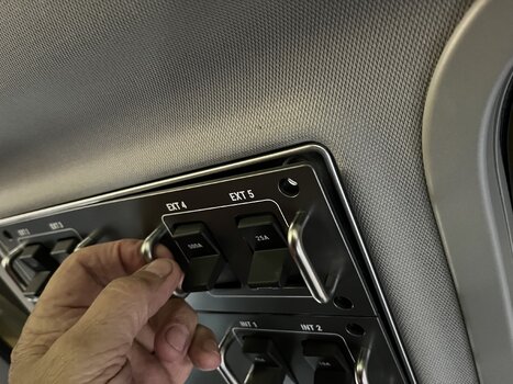
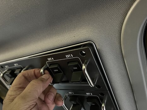
Photo' 2 shows how much I can pry the panel using just my fingers
I have inserted a plastic trim tool but can't see how to lever down without possible damage to fascia trim.
PS
My hands don't look that old and wrinkled in real life.
Attachments
@Cheshire cat You need to use a trim tool and set it at the middle of the panel. The cover ist fixed by three clips. which alinge all in the middle of the cover.
Thank you Pat-Ard. I will take another look.
I want to soundproof around the hands free mic'.
I want to soundproof around the hands free mic'.
Let us all know if it worksThank you Pat-Ard. I will take another look.
I want to soundproof around the hands free mic'.
OK.
All done. Please see pic's
Pic 1 shows the panel with the 12 screws removed (6 in a row, each side)
Pic 2 shows how the plastic panel is still secured by four plastic clips. These can be pried loose with the careful use of a plastic trim tool.
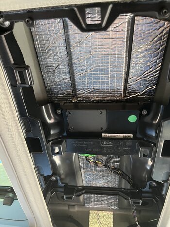
Pic 3 shows the plastic panel now removed. The two arrows at top of the pic is where the two retaining screws can be found. (I suspect that on Bluesurf's build, these are missing, hence why he can pry the whole panel without removing plastic fascia panel.) I did consider not putting these two screws back as the panel is still firmly in place. Decided it might not be a good idea if covering very rough terrain.
The four arrows shown running centre of screen, indicate the fixing locations for the plastic fascia panel.
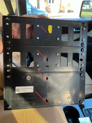
Pic 4 shows the back of the plastic fascia panel. Looking at the fixings, it is surprising how much force was needed to remove from their fixing points as shown in the previous pic.
Pic 5 shows sound deadening foil bonded to the metal surfaces in the hope of improving hands free mic' performance.
Pic 6 shows 25mm (1") sound absorption foam added over the foil. With this in place, and stuffed into the recesses either side I was still able to close the panel without any interference.
I am yet to see if I get any improvements, but for an hours worth of work, well worth a try.
Attachments
Last edited:
Looks like my pics aren't displayed in the same way as I set up for the post. You will have to ignore the pic numbers and work out the rest. I should have changed the jpeg numbers. 
Similar threads
- Replies
- 3
- Views
- 448
- Replies
- 0
- Views
- 328
- Replies
- 4
- Views
- 211
- Replies
- 12
- Views
- 1K

